Do you have a question about the Advanced Electronics Mx-5000 Series and is the answer not in the manual?
Details the standards and directives that the fire alarm control panels comply with.
Provides essential safety warnings and precautions for installation, programming, and maintenance.
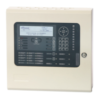
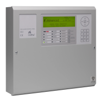
Provides an overview of the manual's scope and the Mx-5000/Mx-5000N series panels.
Describes the panel's graphical liquid crystal display and its functions.
Explains the meaning and function of each LED status indicator on the panel.
Details the zone-specific LED status indications for fire alarm, fault, disabled, or test conditions.
Lists and describes the function of various control buttons on the panel.
Explains the functions of the navigation buttons used for menu interaction.
Describes the use of number and letter buttons for inputting data and navigating menus.
Explains the different sounds produced by the panel's buzzer for fire alarm and fault conditions.
Details the four access levels for panel operation and user permissions.
Describes how the panel indicates and responds to a fire alarm condition.
Explains how the panel indicates and displays fault conditions.
Details how the panel indicates when zones, inputs, or outputs have been disabled.
Describes pre-alarm or plant alarm conditions and their display indication.
Explains supervisory conditions and how they are indicated on the panel.
Describes how the panel displays multiple simultaneous conditions like alarm, fault, and supervisory.
Lists and describes the Level 2 menu functions and their sub-menus.
Explains how to use the panel buttons to navigate through the menu options.
Details how to select specific zone numbers using the number keys within menus.
Describes how to access and view different system statuses like fires, faults, and alarms.
Shows zones and inputs currently in a fire alarm condition.
Shows zones, inputs, and outputs currently in a fault condition.
Shows zones and inputs in an alarm condition, including test states.
Shows inputs and outputs that are currently in a disabled condition.
Shows the current operational status of all zones and individual inputs.
Shows the current operational status of all output devices.
Provides diagnostic information on the panel's software and hardware configurations.
Details the panel's software version, program ID, and checksum.
Provides diagnostic readings for the internal panel electronic circuits and their states.
Provides diagnostic information for other panels or nodes on the network.
Allows viewing of the event history, fire alarms, or alarm counter.
Displays a chronological log of system events, including time, date, and type.
Records and displays the number of times a fire alarm condition has occurred.
Obtains diagnostic information on the network connection and status of other panels.
Provides information on warning conditions, typically indicating detector drift.
Allows viewing of supervisory conditions, such as valve status or low pressure.
Provides options to disable zones, inputs, outputs, controls, user IDs, or groups.
Allows disabling of zones or individual input devices.
Enables the isolation of specific or all output devices.
Disables all sounder outputs on the panel.
Disables all beacon outputs on the panel.
Disables all fire routing output circuits.
Disables all fire protection output circuits.
Disables all fault routing output circuits.
Disables all other types of relay outputs.
Disables all pager outputs.
Allows selection and disabling of individual output devices.
Disables panel controls, effectively returning the panel to Level 1 operation.
Cancels the current user ID and returns the panel to the default User 1.
Disables or enables custom groups of devices across the network.
Provides functions to re-enable disabled zones, inputs, outputs, groups, or remote access.
Re-enables previously disabled zones or individual input devices.
Re-enables disabled output devices such as sounders, beacons, or routing outputs.
Re-enables user-defined disablement groups.
Allows enabling or disabling of remote access for panel operations.
Allows configuration and management of investigation delay modes.
Cancels the Investigation Delay mode, disabling Stage 1/Stage 2 functions.
Enables Investigation Delays and related functions like manual or automatic operation.
Extends current automatic delays, for example, for overtime working.
Prevents pre-programmed delays from activating during specific holiday periods.
Provides functions for testing zones, displays, buzzers, and outputs.
Tests specific call points or detectors in one or more zones.
Checks the operation of all panel indicators and the graphic display.
Tests the internal buzzer by making it sound for a short period.
Invokes a test print sequence to verify printer functionality.
Allows individual testing of output devices like sounders or relays.
Provides access to tools for printing, printer setup, and time changes.
Enables printing of various system data like inputs, outputs, faults, and logs.
Details the serial communication settings required for an external printer.
Allows configuration of printer characteristics and automatic event printing.
Prints information on all input points for selected zones.
Prints information on all output points for selected zones.
Prints information on zones currently in a fault condition.
Prints information on zones with disabled inputs or outputs.
Prints information from the History Log, with options for all events or just fires.
Advances the paper in the printer.
Allows the clock time and date to be changed on the panel.
| Brand | Advanced Electronics |
|---|---|
| Model | Mx-5000 Series |
| Category | Control Panel |
| Language | English |