Page 24 of 42
3.9.7.2 Local Hardware
The Local Hardware Option provides a diagnostic readout of the operational condition and readings
for the internal panel electronic circuits of this panel. When the option is selected, the display shows
a list of the circuits. For example:
[Panel Circuits]
DESCRIPTION VALUE STATE
Sounder A 5.6V Normal
Sounder B 5.6V Normal
Sounder A Load 0mA Normal
Sounder B Load 0mA Normal
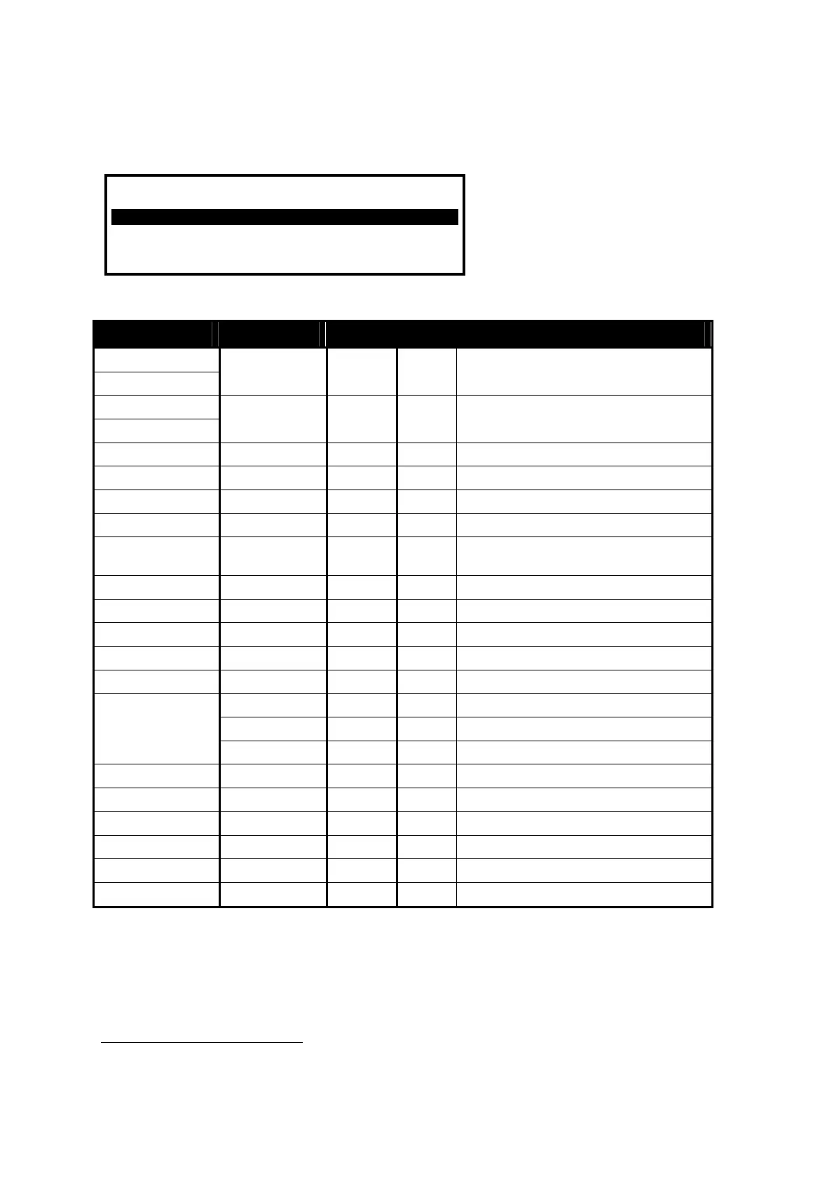
The following table lists the internal panel circuits and indicates the values that can be displayed.
Description Value Range Normal Possible States
Sounder A
Sounder B
4
0V – 14V 5.5V Normal Open Circuit, Short Circuit
Sounder A Load
Sounder B Load
4
0mA – 1000mA
5
Normal Too High
Battery 0V – 30V 27.6V Normal Too High, Too Low
Charger 0V – 30V 28.0V Normal Too High, Too Low
Charger Current 0mA – 2000mA
5
Normal
Charger Temp (C) 0C – 50C
5
Normal
Earth Volts 0V – 30V 2.5V /
14.5V
6
Normal Too High, Too Low
System Volts 19V – 30V 28.0V Normal
Aux Load 0mA – 500mA
5
Normal Too High
1
st
Loop Load
7
0mA – 500mA
5
Normal Open Circuit, Too High, Short Circuit
1
st
Loop V.Out
7
24V – 32V
5
Normal
1
st
Loop V.In
7
24V – 32V
5
Normal
L/H L Normal Programmable inputs
Normal
Panel Switch Inputs
1-9
L/H L Normal
Relay 1 – – Normal
Relay 2 – – Normal
Relay 3
8
– – Normal
Relay 4
8
– – Normal
Main Supply – – Normal
Pager – – Normal
Press the ÏÐ buttons to scroll through the panel internal circuits. Press the ‘Esc’ button to return to
the main view menu.
NOTE: Additional panel circuits may be shown depending on the system configuration and installed
options.
4
The MX-5400 also displays Sounders C and D.
5
Depends on the panel configuration, installation and current operating condition (i.e. fire alarm).
6
Depends on configuration of the panel.
7
Loop Load, V.Out and V.In displayed for each loop driver (2 on MX-5200, 4 on Mx-5400).
8
Requires the installation of the 2-Way Relay card option.