46
The Advanced
®
Model 3250/4250 Service Manual
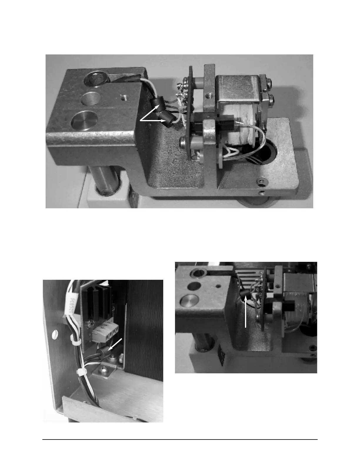
Installation Option A:
Ferrite Beads
Ferrite Bead
Installation Option B:
NOTE: For installation option A, two ferrite beads are installed on the white wire exiting the head shaft
and attached to TR2 on the head transition board.
NOTE: For installation option B, one ferrite bead is locat-
ed on the light blue wire running between PCB522
pin 4 and J3B. The second ferrite bead is located
on the white wire exiting the head shaft and
attached to TR2 on the head transition board.
Ferrite Bead