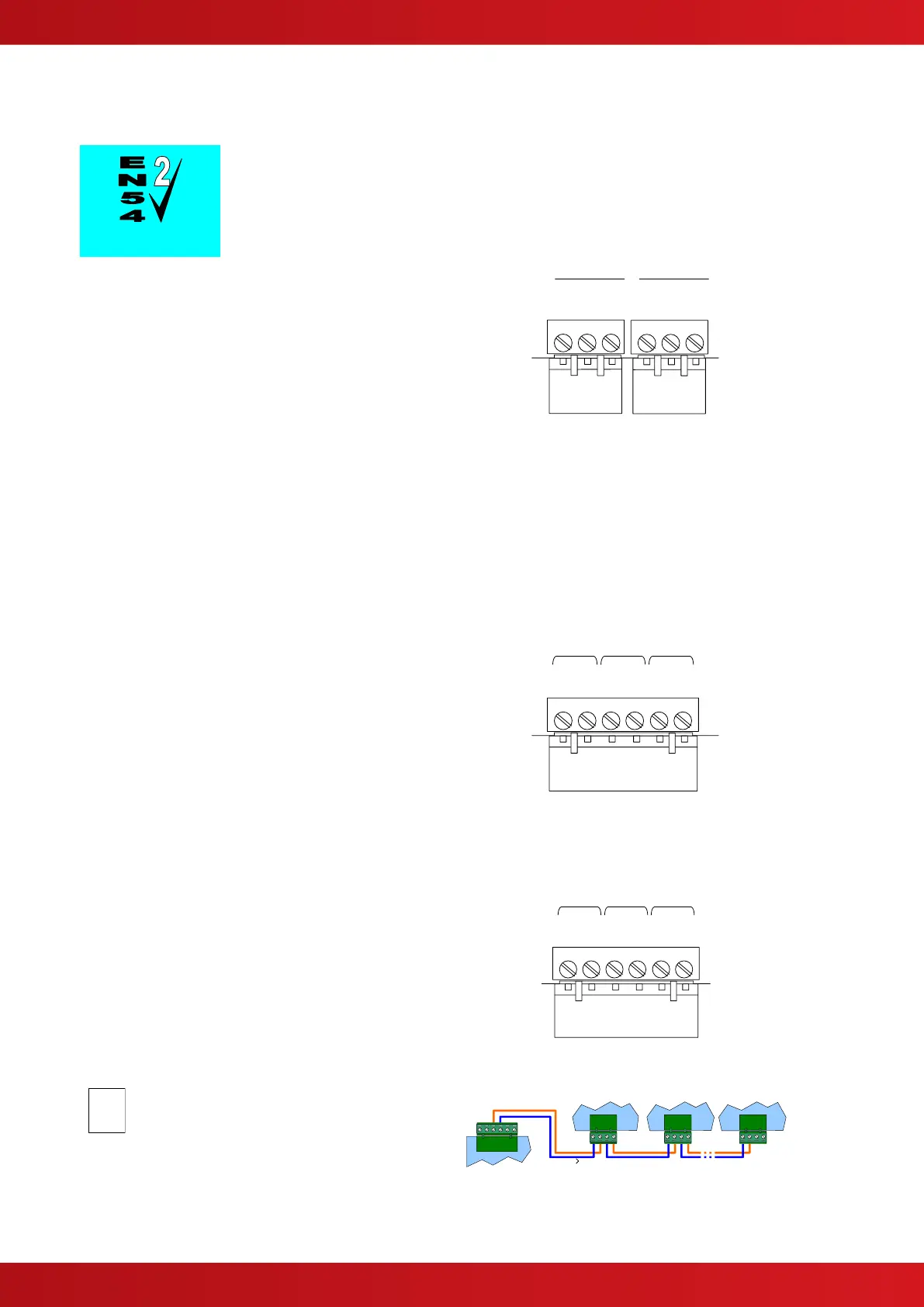
2.5.6 Relay Circuits
Fault Output.
Relay 1 is arranged for failsafe operation as standard.
The MxPro 5 Series are equipped with two relay
outputs. These are normally programmed to
activate on Fault and Fire Alarm conditions
respectively.
Each output is unsupervised with volt-free
changeover contacts rated at 30V AC/DC,
1 Ampere, resistive.
An Optional plug-in 2-Way relay card is available if
additional relays are required (Relays 3 & 4).
Optional peripheral bus relays cards are also
available.
The Relay outputs can be used, instead of the Routing Interface Card, to provide non-monitored fire
and fault routing outputs to appropriate routing equipment.
In this case, the panel will not indicate transmission path failures to the routing equipment – this feature
must be incorporated into the routing equipment itself. [Not fully EN54-2 compliant].
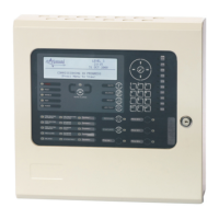
2.5.7 Auxiliary Supply Output
The MxPro 5 Series are equipped with an auxiliary
24V DC, 500mA power supply output.
This can be used for powering ancillary equipment
and must only be used for powering localised /
internal equipment.
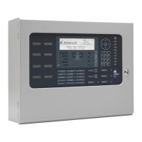
2.5.8 Isolated Peripheral Bus Interface
The isolated bus interface is used to connect local
peripheral equipment located internal to the panel
or located within 10m of the panel.
The terminal block on the MxPro 5 Series base
card is shown opposite. Connect the cable from 'A'
to 'A' and from 'B' to 'B'. Equipment is connected
via a daisy chain.
External connections should be made using fire
rated cable or run in rigid metal conduit between
enclosures.
Peripheral Bus modules must be
configured using the PC Tool
Last Module – FIT
EOL Jumper to IN