1 Installation
1.1 Fitting the Card in a Panel
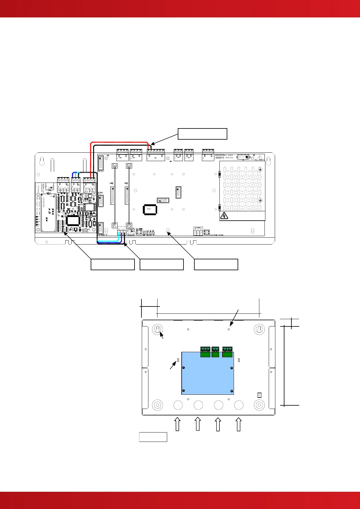
Mount the card to the pillars on the chassis plate using the four M3 screws supplied.
Connect 24V DC supply from the AUX output to the connections on the Pager Interface.
OBSERVE POLARITY!
Connect the RS232 serial connection between the base card and the Pager Interface.
Connect:
TX – RX,
RX – TX
GND – GND
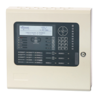
1.2 Mounting the Boxed Version
The enclosure dimensions and fixing
points are shown in the diagram
opposite.
Connect 24V DC supply from the AUX
output to the connections on the Pager
Interface.
OBSERVE POLARITY!
Connect the RS232 serial connection
between the base card and the Pager
Interface.
Connect:
TX – RX,
RX – TX
GND – GND
Run the cabling in rigid conduit or use
fire rated cable. Note: Maximum
distance of 3m (10ft) between the FACP
and the interface.
WARNING: HIGH VOLTAGE INSIDE
DO NOT REMOVE COVER
No Serviceable Parts Inside
Earth Termination
Points x4
Back Box Fixing
Points x4
Recommended
Knockout Usage
www.acornfiresecurity.com
www.acornfiresecurity.com