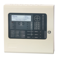
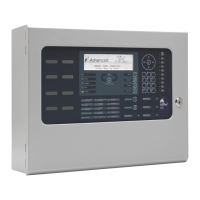
The Pager Interface is a device designed to integrate with fire alarm control panels (FACP) to send event notifications to pager systems. It supports the ESPA 4.4.4 protocol and is compatible with Multitone pager systems. The device can be installed as a card within a compatible FACP or as a boxed version for broader compatibility.
Function Description:
The primary function of the Pager Interface is to translate events from a fire alarm control panel into messages that can be sent to a pager system. This allows for real-time notification of various events, such as fire alarms, test alarms, plant alarms, pre-alarms, faults, and disablements, to personnel carrying pagers. The interface is highly configurable, allowing users to define which events trigger a page, to which pagers or groups of pagers the messages are sent, and the content of these messages.
The device features RS232 galvanic (opto) isolated communication for both the panel and pager interfaces, ensuring robust and reliable data transfer while providing electrical isolation. It includes a fault input that can be monitored and configured for normally open or normally closed relay contacts, with an option to invert the signal.
Configuration of the Pager Interface is done via a dedicated PC program called MxPager. This software allows for detailed customization of the interface's operation, including communication settings, event-to-pager assignments, pager groups, shift times, and pager zones. The configuration can be uploaded from the PC to the Pager Interface using a standard RS232 upload/download lead.
Important Technical Specifications:
- Models:
- Mxp-547: Pager Interface Card
- Mxp-547-BX: Pager Interface (Boxed)
- Power Supply: 15-30V DC (wired from panel 24V auxiliary supply).
- Supply Current: 50mA (typical at 24V DC).
- Temperature Range: -5°C to 50°C.
- Humidity: 95% (non-condensing).
- Dimensions:
- PCB: 85mm H x 105mm W x 15mm D.
- Enclosure (Boxed Version): 218mm H x 300mm W x 45mm D.
- Panel Interface: RS232 Galvanically (Opto) isolated.
- Pager Interface: RS232 Galvanically (Opto) isolated.
- Fault Input: Non-monitored / Monitored (10K EOL, 470R active).
- Maximum Number of Pagers: 250.
- Maximum Number of Groups: 50.
- Maximum Number of Pagers per Group: 8.
- Event Types Supported: Fire Alarm, Test Alarm, Plant Alarm, Pre-Alarm, Fault, and Disablements.
- Software Version: Operation and functions available from Software Version Mx5000-050-04 onwards.
- Communication Settings:
- Baud Rate: Configurable (600, 1200, 2400, 4800, 9600, 19200, 38400, 57600). Default: 4800.
- Data Bits: Configurable (7, 8). Default: 8.
- Stop Bits: Configurable (1, 2). Default: 1.
- Parity: Configurable (None, Odd, Even). Default: None.
- CTS: Configurable (Disabled, Enabled, Switched). Default: Disabled.
Usage Features:
- Installation Flexibility: Available as a card for integration into medium, large, and deep Mx-5000 Series panels, or as a boxed version (Mxp-547-BX) compatible with all Mx-5000 Series panels.
- Serial Communication: Connects to the FACP via RS232 serial connection (TX-RX, RX-TX, GND-GND). Maximum cable distance of 3m (10ft) between FACP and interface, requiring rigid conduit or fire-rated cable.
- Power Connection: Requires a 24V DC supply from the FACP's AUX output, with strict observance of polarity.
- Status Indications:
- Heartbeat LED: Flashes at 1Hz to indicate normal operation.
- RS232 Activity LEDs (LED1, LED2, LED9, LED10): Indicate data transmission and reception from both the fire panel and the pager system.
- Configuration Software (MxPager):
- General Options:
- Limit Number of Detector Faults: Prevents swamping the pager system with excessive fault messages (configurable from 1 to 250 faults per hour).
- Philips Pager Option: Specific setting for Philips pager systems.
- Monitor Fault Input: Enables or disables the fault input circuit.
- Invert Fault Input: Inverts the signal for monitoring Normally Open relay contacts.
- Retransmission: Allows configuration of retransmission for persistent events, including interval (1-30 minutes) and number of retransmissions (1-255). An "ALL CALL" group can be configured to receive messages after all normal retransmissions have occurred.
- Text Cuts: Enables customization of pager messages by selecting specific system information (Device Text, Zone Text, Event Text, Point Address, Event Time, Zone Number) and/or user-defined text. This feature allows for concise messages, accommodating pagers with limited display capabilities. Up to four text cuts can be defined, with maximum lengths for each item (e.g., Device Text 26 chars, Zone Text 32 chars).
- Pager Events: Configures which pagers or pager groups receive notifications for specific event types (Fire, Alarm, Plant Alarm, Pre-Alarm, Fault, Disable). Allows setting beep codes (0-9) and custom event text (up to 16 characters).
- Pager Groups: Simplifies event programming by allowing up to 50 groups, each containing up to 8 individual pager addresses. Pager addresses can be 4 digits long, including numbers (0-9), characters (A-F), or wildcards (*).
- Shift Times: Defines up to 8 shifts per day for weekdays and weekend days, configurable in five-minute intervals, to manage pager assignments based on time.
- Pager Zones: Assigns specific zone ranges (1-2000) to individual pager addresses, ensuring that pagers only receive events relevant to their designated areas. Up to two zone ranges can be defined per pager address.
- Printer Integration: If a printer is required, an internal Mxp-512 printer assembly can be fitted.
Maintenance Features:
- Fault Code Reporting: The device reports various fault conditions to the Panel LCD, aiding in troubleshooting. These include:
- DEVICE MISSING: Pager interface not responding to panel communications.
- CORRUPT DATA: Communications between panel and pager affected.
- PROGRAM FAIL: Checksum error in operating program, requiring re-flashing with MxFlasher Tool.
- CONFIG. FAIL: Checksum error in configuration data, requiring power cycle and re-configuration with MxPager Tool.
- NOT READY: Interface not configured or partially configured, possibly due to RS-232 lead disconnection during upload.
- CPU RESET: Device powered up or reset by watchdog timer.
- DEVICE FAULT: Pager interface cannot establish communications with ESPA Paging system.
- OPEN CIRCUIT / SHORT CIRCUIT: Fault input wiring issues (check EOL resistor).
- INPUT FAULT: Fault input in active condition from ESPA Pager system (check configuration and ESPA Pager system).
- Normal: Interface and Fault Input in normal operating condition.
- Configuration Upload/Download: Easy transfer of configuration data between PC and Pager Interface using the MxPager software and a serial lead.
- Commissioning Mode: Transmission to the Pager Interface is prevented when the FACP is in COMMISSION mode, preventing unwanted messages during testing.