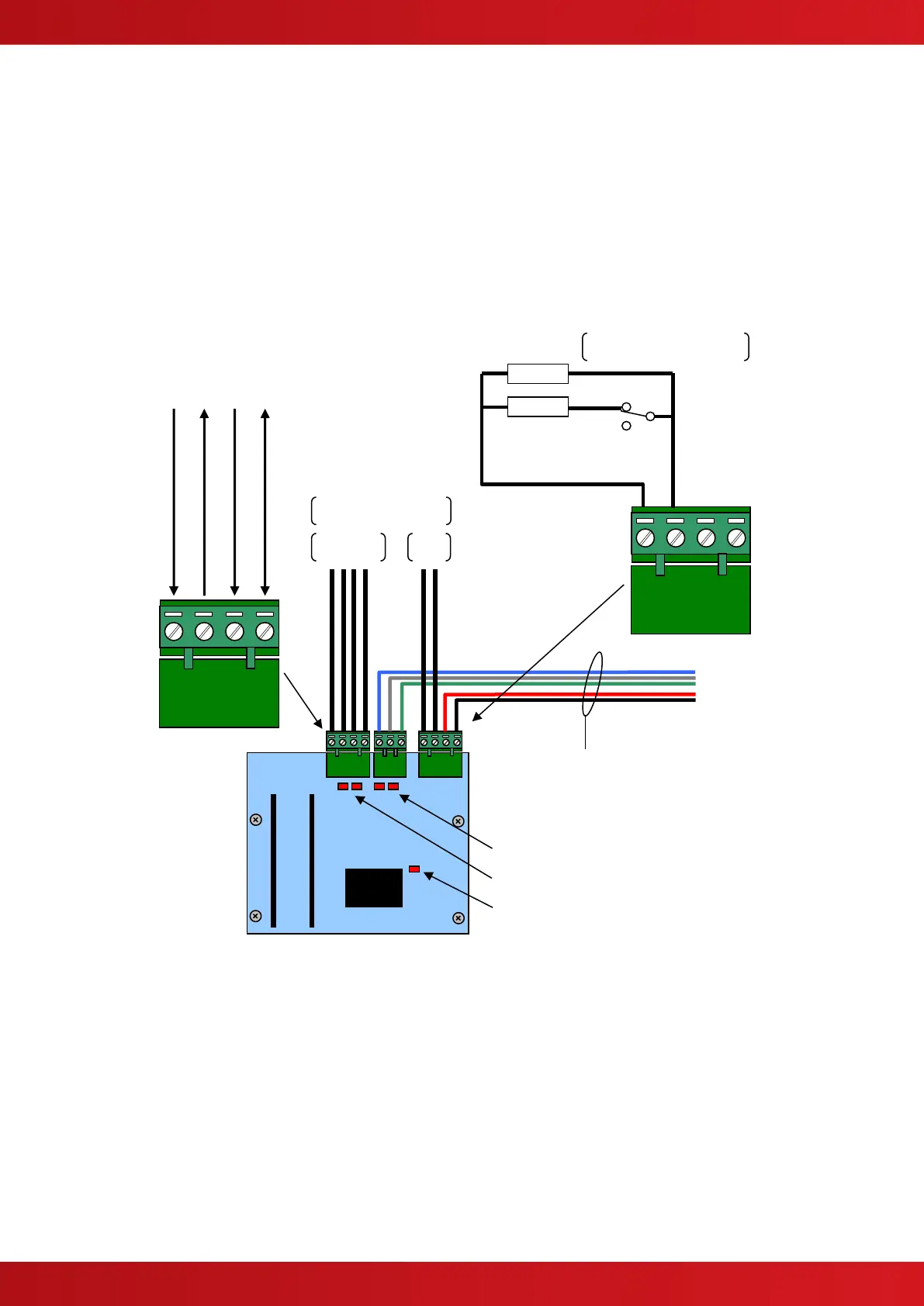
1.1 Status Indications
Status indications are provided on the card to show operation of the interface.
1.1.1 Heartbeat LED Indicator
The Heartbeat LED will normally flash at a rate of 1Hz (once per second) to indicate that the card is
operating.
1.1.2 RS232 Activity LEDS
LED2: RS232 RX – Lit when data is received from the fire panel.
LED1: RS232 TX – Lit when data is transmitted to the fire panel.
LED10: RS232 RX – Lit when data is received from the pager.
LED9: RS232 TX – Lit when data is transmitted to the pager.
1.2 Wiring to the Pager Interface
The Serial Interface follows the standard RS232 interface connections. Run the cabling in rigid conduit or use
fire rated cable. Note: Maximum distance of 3m (10ft) between the Interface and the Pager.
Connect the TX terminal of the interface to the RX (RXD-Receive) input of the pager.
Connect the RX terminal of the interface to the TX (TXD-Transmit) output of the pager.
Connect the GND terminal of the interface to the 0V or GND terminal of the pager.
Interface to the ESPA
Pager System
CTS (Clear to Send from Pager)
Fault Input Arrangement
Monitored Input
www.acornfiresecurity.com
www.acornfiresecurity.com