2.5.4 Sounder Circuits
The 5100 & 5200 are equipped with two
supervised sounder circuits. These are denoted
as Circuits A and B.
The 5400 is equipped with four supervised
sounder circuits. These are denoted as Circuits A,
B, C and D.
Each Sounder output is rated at a maximum of
1 Ampere.
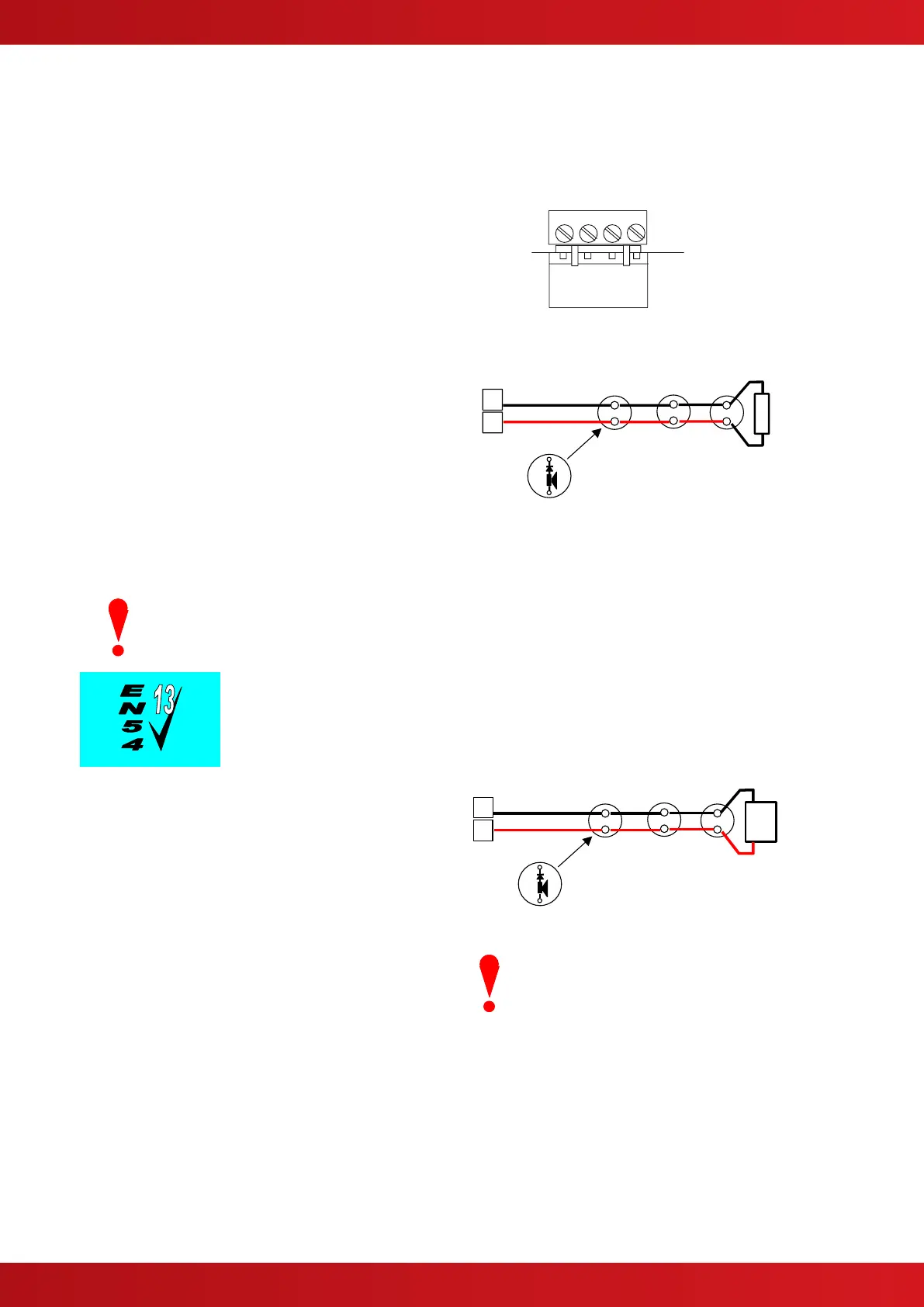
The terminal connections on the base card are
shown in the diagram opposite.
Base Card Connections – Typical.
The sounder outputs are monitored (supervised)
for open and short circuit conditions using reverse
polarity signals. Sounder must be equipped with
an in-built blocking diode that prevents the
sounder from taking power when the output is in
the supervising condition.
An End-of-Line Resistor (EOLR) of value 6200,
½ Watt must be fitted to the last sounder / bell.
Refer to Appendix 2 – Recommended Fire Rated
Cables for further information on cable types to be
used.
Typical Sounder Arrangement.
When screened cable is used, it is vital to connect the screen to the chassis / earth at the cable
gland input / earth stud in the panel. Always ensure that all segments of the cable loop have
continuity of the screen and take care to ensure that the screen is not exposed to any other
earth point (e.g. metalwork, cable trays, junction boxes, etc.).
The sounder outputs support monitoring with an Active EOL device to ensure
circuit integrity in accordance with the requirements of EN54-13.
The sounder circuits can be configured for
compliance with EN54-13 by programming and
the use of an Active EOL device. All panel
sounder outputs must be fitted with the Active
EOL device (Mxp-505)
The panel uses techniques to ensure that a fault
warning condition is reported if the circuit
resistance increases to a condition where the
voltage at the last device may fall below its
minimum operating voltage level. This is
compatible for load currents from minimum up to
maximum (1 ampere).
Install the Active EOL device at the end of the
sounder circuit instead of the normal EOL resistor
– this device is polarity sensitive. Connect the Red
lead to the sounder + signal line.
Typical Sounder Arrangement.
OBSERVE POLARITY
The Active EOL device is polarity
sensitive.
The Active EOL is fuse protected –
however, if connected incorrectly
and the sounder circuit is activated,
the fuse will open and is not user
replaceable.
www.acornfiresecurity.com
www.acornfiresecurity.com