Position
10 9 8 7 6 5 4 3 2 1
2.5.9 Switch Inputs
2.5.9.1 Base Card
One Switch input is provided on the base card
(I/P9) and up to eight key switch inputs (I/P1-8)
are provided on the display card.
These can be used for changing access level,
performing “class change” etc. by changing the
“Action” of these inputs.
Refer to separate Application Notes for examples.
The base card switch input is a monitored circuit –
EOL = 10KΩ,
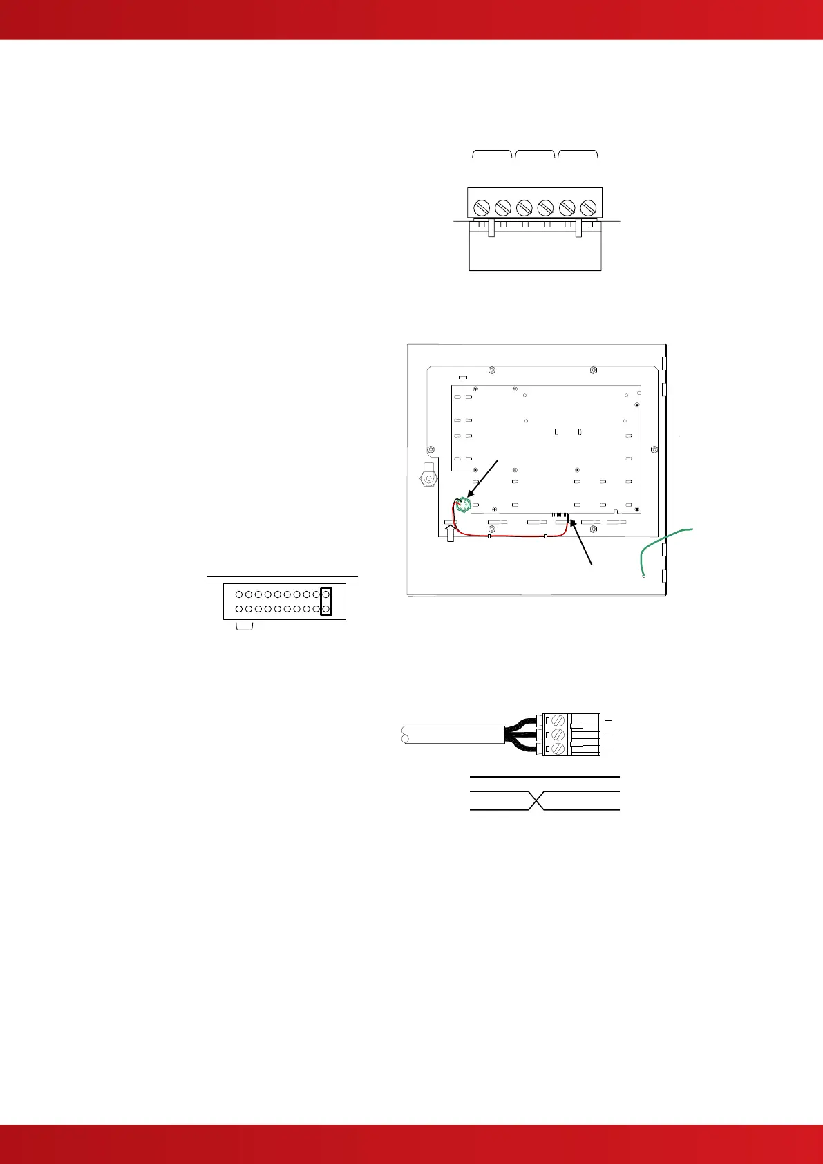
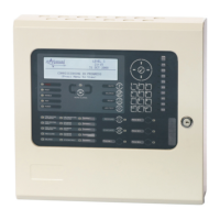
2.5.9.2 Display Card
Optional key switches (volt-free) are available to
be mounted on the panel fascia plate. These are
pre-wired with the appropriate 2-pin connector.
Using a sharp knife, cut through the fascia label
using the aperture profile as a template. Insert the
switch mechanism and tighten the nut. Route the
wiring as shown and plug into the connector.
Program the required function.
The fascia label is provided with a slide-in label
pocket for a user text
description.
The switch cable
connector plugs into
the display card
connector as show
opposite.
Route the switch cables
along the bottom of the
fascia plate and fix with
tie-wraps to the return
flange.
Display Plate Arrangement (Typical).
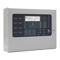
2.5.10 RS232 Interface
The Mx-5000 Series are equipped with an isolated
RS232 I/F Circuit at the bottom of the base card.
The terminal block connections are shown
opposite.
TX = Transmit Data from the panel, RX = Receive
Data into the panel, GND = Ground Reference.
This interface can be used for connection to a
modem, pager interface, PC or external printer.
Base Card Connections – typical.
2.5.11 USB Interface (Type B)
The Mx-5000 Series are equipped with an isolated USB I/F Circuit at the bottom left of the base card.
This can be used for connection to a PC for use of the PC Configuration Tool.
The USB Interface uses common signals with the RS232 Interface – plugging in a USB connection
disconnects and isolates the RS232 Interface.
www.acornfiresecurity.com
www.acornfiresecurity.com