3.3.20 Output Groups
The “Cause and Effect” programming is a schedule of actions that will turn on one or more outputs dependant
on a set of input events.
The Outputs Option provides the means to create simple or complex “cause and effect” programming within the
panel. Delays can be introduced to allow a phased evacuation of a building (Note this is different to an
“Investigation Delay” which is detailed in section 3.3.21).
This section describes the settings and options in detail for each parameter. Refer to Appendix 4 – Cause and
Effect Programming Example for a description of how to program a typical requirement.
More complex “Cause and Effect” programming may be undertaken using the PC Configuration tool.
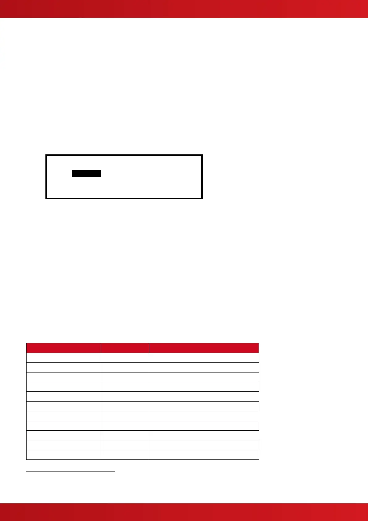
When the OUTPUTS Option is selected, the display shows the cause and effect programming for Output Group
1. For example:
[Output Group 1] [ 3.9% Mem used]
ZONE CAUSE STYLE=Delay->MODE Wait
1 ANY FIRE 00 - On
2 ANY FIRE 00 - On
3 ANY FIRE 00 - On
4 ANY FIRE 00 - On
To simplify the cause & effect programming, one or more outputs that will respond in the same way when the
same set of input events occurs can be grouped together. This association of outputs is called an Output Group.
The panel can support up to 200 of these Output Groups.
To select a different Output Group, press the button to highlight the Output Group Number field and then
enter the number of the output group required using the number buttons. The display always shows the Output
Group is shown in the top left corner.
Press the buttons to scroll through the list of zones.
Press the buttons to select the fields for a particular zone.
Press the ✔ button to select a particular field option to change its setting.
3.3.20.1 Default Output Settings
On initial installation, or after clearing the configuration memory, all outputs are assigned to specific Output
Groups and will turn on immediately a single fire alarm occurs in any zone (any fault condition for the fault
relay). The default assignments are as follows:
Any fire in any zone – no delay
Any fire in any zone – no delay
Any fire in any zone – no delay
Any fire in any zone – no delay
Any fault in any zone – no delay
Any fire in any zone – no delay
On-board Open Collectors
14
Any fire in any zone – no delay
Any fault in any zone – no delay
Any fire in any zone – no delay
Any fire in any zone – no delay
Any fire in any zone – no delay
Mx-5400 Only
This Output is used for routing if the non-monitored routing option is selected.
This Output is available on the optional Routing Interface Peripheral Card.
www.acornfiresecurity.com
www.acornfiresecurity.com