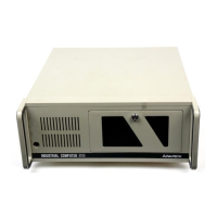
IPC-610 User's Manual
iii
Table of Contents
Chapter 1 General Information...................................................................................................1
1.1 Introduction ............................................................................................................................................... 1
1.2 Specifications.............................................................................................................................................. 1
Figure 1-1: IPC-610 dimensions ........................................................................................................................ 2
1.3 Dimensions ................................................................................................................................................. 2
Chapter 2 System Setup ...............................................................................................................3
2.1 Removing the Cover .................................................................................................................................. 3
Figure 2-1: Removing the cover ........................................................................................................................ 3
Figure 2-2: Removing the drive bay ................................................................................................................. 3
Figure 2-3: Inserting the drives into the drive bay .......................................................................................... 3
2.2 Adding Your Disk Drives.......................................................................................................................... 3
2.3 The Hold-down Clamp .............................................................................................................................. 4
Figure 2-4: Detaching the hold-down clamp .................................................................................................... 4
Figure 2-5: Inserting the rubber buffers .......................................................................................................... 4
2.4 Connecting the Keyboard ......................................................................................................................... 4
Figure 2-6: Front keyboard connection............................................................................................................ 4
Figure 2-7: Rear keyboard connection ............................................................................................................. 4
2.5 Replacing the Filter ................................................................................................................................... 5
Figure 2-8: Replacing the filter ......................................................................................................................... 5
Appendix A Rear Cover and Window .......................................................................................6
A.1 Changing the Rear Cover According to Power Supply Used ................................................................ 6
Figure A-2: IPC-610 with redundant power supply........................................................................................ 6
Figure A-1: IPC-610 with PS/2 size power supply........................................................................................... 6
A.2 The Backplane........................................................................................................................................... 7
Figure A-3: Rear window of IPC-610 for standard 14-slot backplane, with PS/2 size power supply ........ 7
A.3 AT Motherboard....................................................................................................................................... 8
Figure A-4: Rear window of IPC-610 for standard AT motherboard .......................................................... 8
A.4 ATX Motherboard.................................................................................................................................... 9
Figure A-5: IPC-610 ATX chassis component layout ..................................................................................... 9
Figure B-1: IPC-610 exploded diagram (internal components) ................................................................... 10
Appendix B Exploded Diagrams ...............................................................................................10
Figure B-2: IPC-610 exploded diagram (case components) ......................................................................... 11
Figure B-3: IPC-610 exploded diagram (speaker, LED, fan) ....................................................................... 12
Appendix C Safety Instructions.................................................................................................13
Safety Instructions ............................................................................................................................................ 13
Wichtige Sicherheishinweise ............................................................................................................................ 14