4
IPC-610 User's Manual
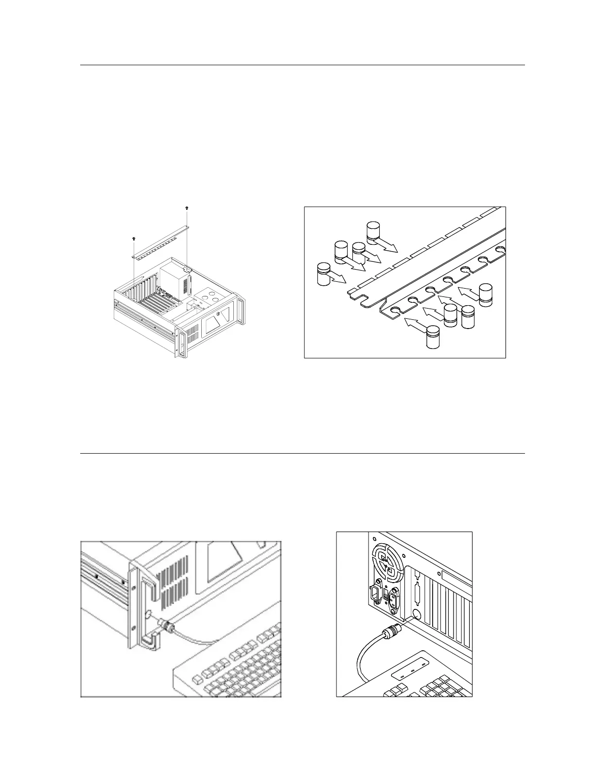
2.3 The Hold-down Clamp
The IPC-610 uses a hold-down clamp to ensure the plug-in cards are securely fastened. It also offers
protection against shock and vibration. To install your cards into the passive backplane, proceed as
follows:
1. Detach the hold-down clamp by removing the two screws located at each end and lifting it off the
chassis. (See Fig. 2-4)
2. Insert the rubber buffers (provided) into the hold-down clamp. These buffers offer the plug-in cards
two levels of protection against vibration. (See Fig. 2-5)
Figure 2-4: Detaching the hold-down clamp Figure 2-5: Inserting the rubber buffers
Figure 2-6: Front keyboard connection Figure 2-7: Rear keyboard connection
2.4 Connecting the Keyboard
Two 5-pin DIN keyboard connectors, wired in parallel, are provided. One is on the front panel, near the
fan intake, and one is on the rear of the chassis, next to the power supply. You may connect your
keyboard to either. Note that both connectors are notched for correct orientation. (See Figs. 2-6 and 2-7
below.)