EasyManua.ls Logo

Advantech PCM-3365 User Manual

Advantech PCM-3365
82 pages
To Next Page IconTo Next Page
Page #1 background imageLoading...
Page #1 background image
The information contained in this document has been carefully researched and is, to the best
of our knowledge, accurate. However, we assume no liability for any product failures or
damages, immediate or consequential, resulting from the use of the information provided
herein. Our products are not intended for use in systems in which failures of product could
result in personal injury. All trademarks mentioned herein are property of their respective
owners. All specifications are subject to change without notice.
Manual
PCM-3365
Advantech
Our company network supports you worldwide with offices in Germany, Austria,
Switzerland, Great Britain and the USA. For more information please contact:
FORTEC Elektronik AG
Büro West
Hohenstaufenring 55
50674 Köln
Telefon: +49 (0) 221 272 273-0
Telefax: +49 (0) 221 272 273-10
E-Mail:
west@fortecag.de
Internet: www.fortecag.de
ALTRAC AG
(Tochter der FORTEC):
Bahnhofstraße 3
CH-5436 Würenlos
Telefon: +41 (0) 44 7446111
Telefax: +41 (0) 44 7446161
E-Mail:
info@altrac.ch
Internet: www.altrac.ch
Question and Answer IconNeed help?

Do you have a question about the Advantech PCM-3365 and is the answer not in the manual?

Advantech PCM-3365 Specifications

General IconGeneral
USB4 x USB 2.0
Memory1 x DDR2 SO-DIMM, up to 2GB
Storage1 x CompactFlash
Serial Ports2
Expansion SlotsMini PCIe
Display OutputVGA
AudioRealtek ALC662
Operating Temperature0°C to 60°C
Power Input12V DC
Networking1 x Realtek RTL8111E GbE

Summary

General Information

PCM-3365 Introduction

Overview of the PCM-3365, its features, and expansion capabilities.

PCM-3365 Specifications

Detailed technical specifications including processor, memory, graphics, and I/O.

Block Diagram

Visual representation of internal components and their connections.

Board Layout and Dimensions

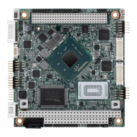
Physical layout of components and dimensions for installation planning.

Installation Procedures

Jumpers and Switches Configuration

Configuration options using jumpers and switches on the board.

Onboard Connectors and Locating

Description and location of onboard connectors for peripherals.

Setting Jumpers

Procedures for setting jumper configurations for system customization.

AMI BIOS Setup Guide

BIOS Setup Introduction and Navigation

Overview of the BIOS setup utility and basic navigation within the interface.

Main Setup Screen

Details of the main BIOS screen options and controls.

Advanced BIOS Features Setup

Configuration options for advanced system features within the BIOS.

Pin Assignments

Jumper List

Detailed list of jumpers, their part numbers, footprints, and functions.

Connector Pin Definition

Pinouts for all onboard connectors, including power, audio, and data interfaces.

System Assignments

System I/O Ports

Address ranges and devices for system I/O ports.

1st MB Memory Map

Memory map for the first megabyte of system memory.

Interrupt Assignments

Mapping of interrupts to system devices and sources.

Watchdog Timer Sample Code

Watchdog Timer Sample Code Example

Example code for implementing the watchdog timer functionality.

Related product manuals