15 UNO-2272G User Manual
Appendix A System Settings and Pin Assignments
A.2 Board Connectors and Jumpers
There are several connectors and jumpers on the UNO-2272G board. The following
sections tell you how to configure the UNO-2272G hardware setting.
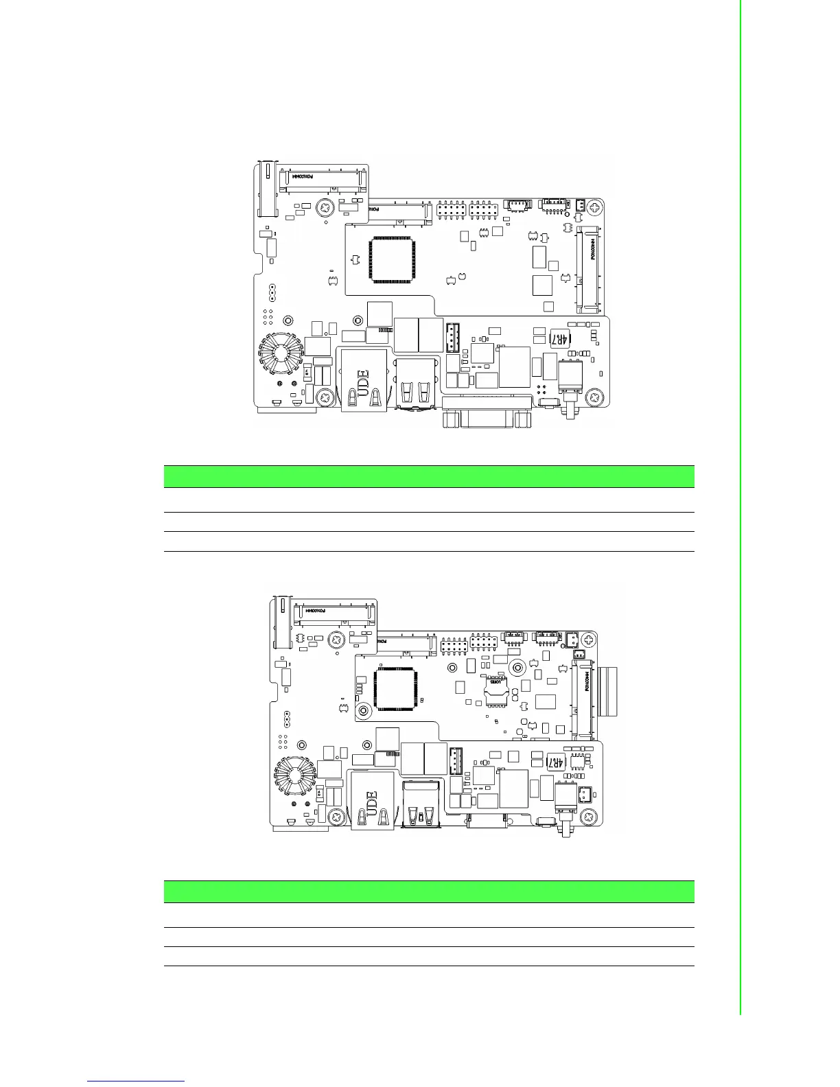
Figure A.1 shows the locations of UNO-2272G’s connectors and jumpers.
Figure A.1 Connector & Jumper Locations for UNO-2272G-N2AE(front)
Figure A.2 Connector & Jumper Locations for UNO-2272G-J2AE(front)
Table A.2: Connectors and Jumpers
Label Function
CN8 CN10 PCI Express mini Card Socket
CN6 mSATA
Table A.3: Connectors and Jumpers
Label Function
CN16 CN10 PCI Express mini Card Socket
CN15 mSATA