6
Note: The Power Switch must be kept in the ‘ON’ position, otherwise, the
UPS will be disabled and your equipment will not be protected during a
power failure.
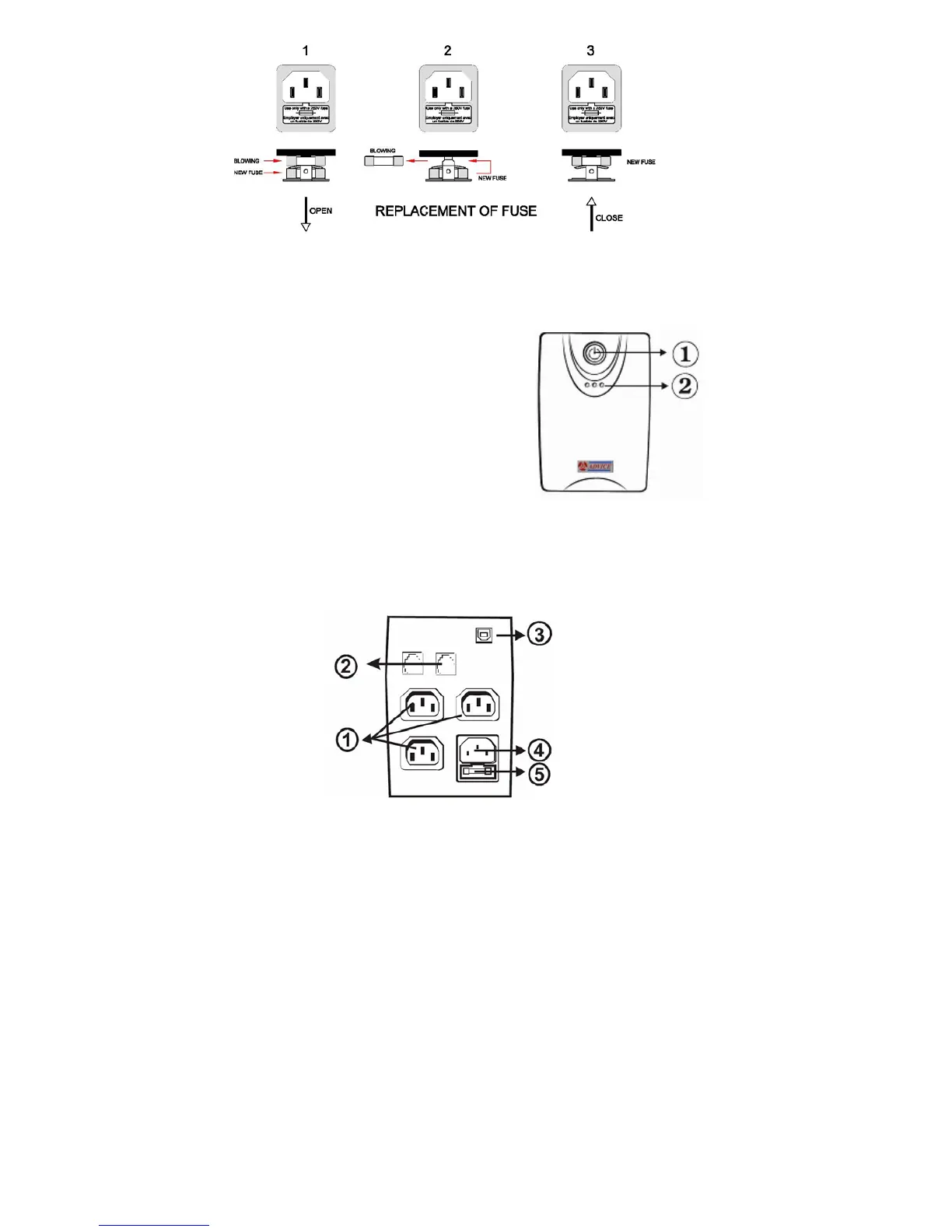
4. System Description
Front panel
1. Power Switch
2. LED Indicators –
AC Mode: Green lighting
Backup Mode: Yellow flashing
Fault: Red lighting
Battery low/replace: Red lighting
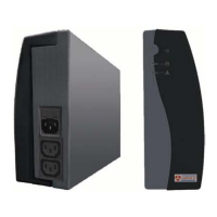
Back Panel
1. Battery Power Supply Outlets
2. Modem/Phone line Surge
Protection
3. USB Port
4. AC Input
5. Fuse