7. Setting
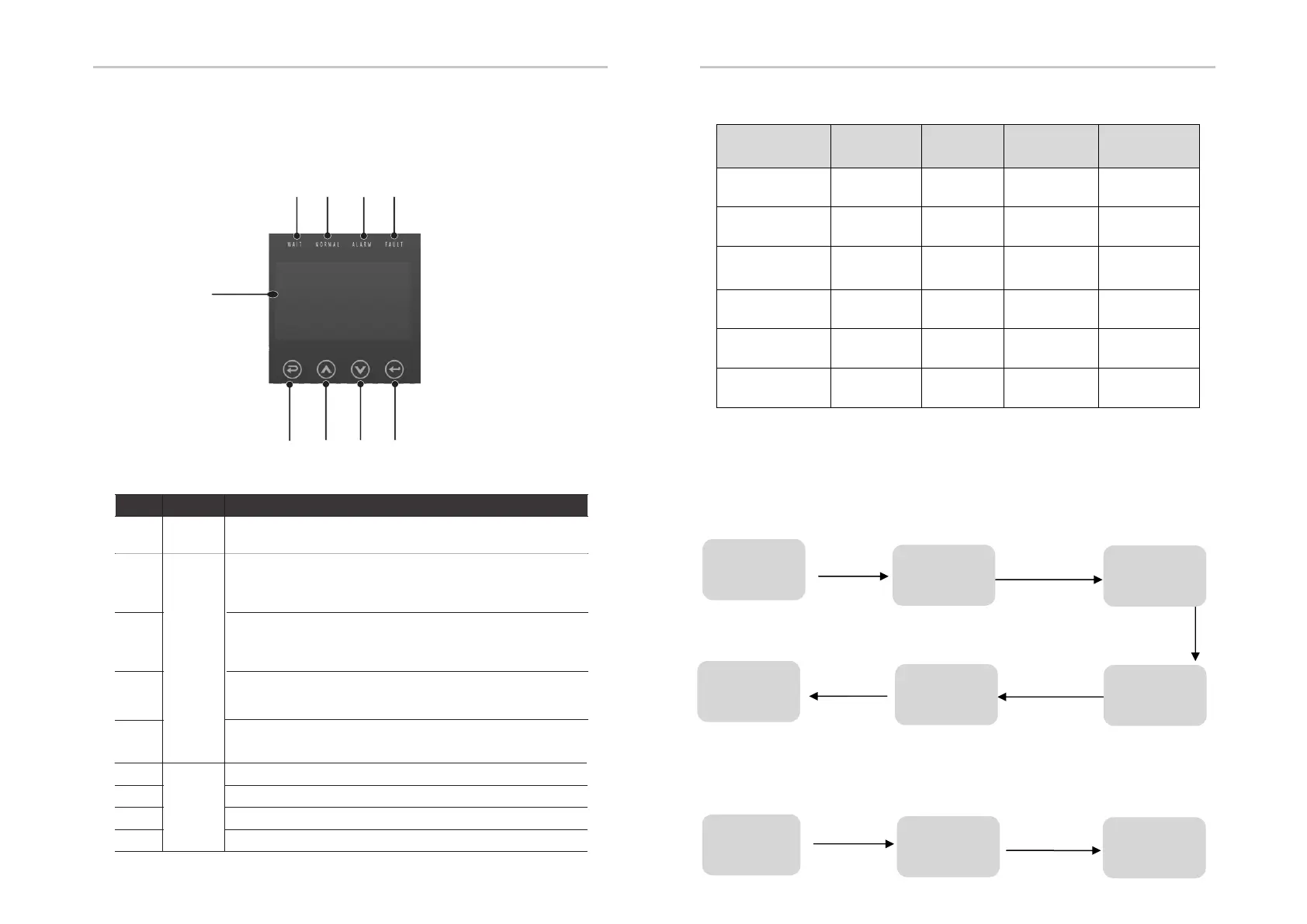
7.1 Control Panel
B
C
D
E
F
G H I
7.2 Instructions for LED Indicator
Indicator
LED
Function
Button
Down button: Move cursor to downside or decrease value.
ESC button: Return from current interface or function.
OK button: Confirm the selection.
Up button: Move cursor to upside or increase value.
LCD
Screen
Display the information of the inverter.
Object
A
B
C
D
E
F
Description
G
H
Name
lit in blue: The inverter is in normal status or in EPS mode.
flash in blue: The inverter is in waiting status.
Off: The inverter is in fault status.
lit in green: The battery communication is normal.
flash in green: The battery is in idle mode.
Off: The communication between inverter and battery is failed.
lit in red: The inverter is in Warning .
Off: The inverter has no Inverter Warning
Setting Setting
40
41
A
I
lit in red: The inverter is in fault status.
Off: The inverter has no errors.
HYBRYD
(
((
(Green)
EPS
(
((
(Green)
ALARM
(Yellow)
FAULT
(Red)
Initialization off off off off
Stand-by off off off off
Hybrid power
connection
on off off off
Off-network off on on off
Bypass of mains flash off on off
Fault off off off on
7.3 Instructions for the use of three modes
(1) Before selecting the mode, you can set it up ac cording to the local power grid,
PV input mode and battery type.
Power grid:
Note: If there are requirements for reactive power in the locality, please refer to
7.3.1 and set up in line with the actual needs.
Select 1 to set up
Press ENTER button
Press ESC button
Initial interface
before powering
on
Default password 00000
Press UP/DOWN button
Adjust the figure
Press ENTER button
Press ENTER button
Press ENTER button
Enter password
Press ENTER button
User
Enter password
3 Grid standards
Choose
according to
local power grid
Restart
Setting
4 Operation
parameters
1 Reactive
power mode