Do you have a question about the AEG Protect 5.31 and is the answer not in the manual?
Instructions must be read by all persons working with or on the UPS prior to installation and start-up. They are a composite part of the UPS.
Operating instructions comply with current technical specifications; contents do not constitute a contract subject matter, but serve for information purposes only.
Goods and services subject to general conditions; alteration of specifications reserved. Claims must be submitted within one week of receipt.
Instructions structured for qualified personnel; illustrations clarify steps. Danger highlighted by pictograms explained in Chapter 1.
Safety regulations must be complied with for personnel safety and unit availability. All personnel must be familiar with them.
Caution: Voltage can be fatal. Disconnect UPS from power supply before work. Capacitors must be discharged.
UPS may only be handled by qualified personnel familiar with safety and installation regulations.
UPS for uninterrupted power supply. Unit for intended purpose only. No unauthorised modifications permitted.
No liability accepted if UPS used for unintended applications. Injury/damage prevention is owner's responsibility.
Utilises electronic high-performance components, suitable for universal applications, high reliability, efficiency, and communication.
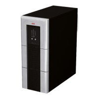
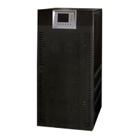
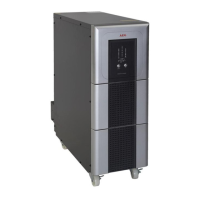
Description of the physical components and their arrangement on the UPS unit, including DOU and ventilation grids.
UPS units packed to withstand transport. Housing fixed to pallet. Plastic film protects surface and moisture.
Instructions for safe crane transport, including safety precautions and lifting requirements.
Guidelines for forklift/lowlift truck transport, emphasising correct weight capacity and avoiding uneven ground.
Suitable floor surfaces and environmental conditions for UPS installation, including space requirements for ventilation.
Details on floor mounting, including hole spacing, diameter, and ensuring vertical alignment.
Describes four possible operating modes: mains, faulty mains, defective inverter, and manual bypass.
Describes battery charging process via CVCC curve, constant current, and trickle charging.
Describes implemented battery tests, their initiation, cancellation, parameters, and prerequisites.
Details terminal strips X1, X4 for supply inputs, X2 for battery, and X3 for loads.
Shows connection panels for UPS models and provides general rules for cable polarity.
Table detailing cross sections and fuse protection for rectifiers, SBS input, load output, and battery connections.
Step-by-step guide for preparing UPS start-up, including switch positions and voltage measurements.
Detailed steps for starting the UPS, including LED indications and display confirmations.
Procedure for disconnecting the UPS in an emergency or for maintenance, including switch actions.
Option for emergency shutdown to disconnect loads via an external contact, depending on customer requirements.
Table listing fuses, their ratings, and the protected components for 10-40 kVA models.
Description of the DOU: display unit, LEDs, graphical LCD, operating panel, and unit status indicators.
Procedure for the initial start-up and commissioning of the DOU and UPS, including language selection and parameterisation.
Accessing status/measured values via operating display to view circuit, battery, and load information.
Accessing the 'Service' menu to set UPS/battery parameters and manipulate operating statuses, requires password.
Guidance on battery charging, including constant current, trickle charging, equalising, and start-up charging.
Setting battery parameters in 'SERVICE / BATTERY VALUES' menu and understanding abbreviations and ranges.
Describes implemented battery tests, their initiation, cancellation, parameters, and prerequisites.
Describes remote signalling PCB, inputs (optocoupler) and outputs (relay contacts) for UPS status.
Two serial interfaces for IT connections using AEG protocol CBSER or other licensed protocols.
Comprehensive diagnostic functions for operational reliability and troubleshooting, including self-diagnosis and data logger.
Table listing common faults, possible causes, and remedies for quick location and elimination.
Recommendation for regular visual checks and functional tests to maintain availability and reliability.
Procedure for checking battery charge, intervals, and specific measurements like voltage and electrolyte temperature.
| Input Voltage | 230 V |
|---|---|
| Output Voltage | 230 V |
| Output Frequency | 50/60 Hz |
| Form Factor | Tower |
| Operating Temperature | 0 - 40 °C |
| Battery Type | Sealed lead-acid (SLA) |
| Communication Interface | USB |
| Output Connectors | IEC C13 |
| Humidity | 0-95% non-condensing |
| Storage Temperature | -15-45°C |