Do you have a question about the AEG Protect PV 2000 and is the answer not in the manual?
Details risks and precautions related to electric shock hazards within the PV-Inverter.
Outlines the conditions, duration, and coverage of the product's warranty.
Explains the steps to follow when making a warranty claim for the inverter.
Details specific conditions and situations not covered by the product warranty.
Describes the option to extend the standard factory warranty for the PV-Inverter.
Details the steps for unpacking the PV-Inverter and checking its contents.
Lists important considerations and checks required before proceeding with the installation.
Provides instructions and guidelines for securely mounting the PV-Inverter onto a wall.
Explains the process and requirements for connecting the PV-Inverter to the AC power grid.
Details how to connect the PV panels to the DC input terminals of the PV-Inverter.
Describes the final checks and verification steps after installation and connections are made.
Explains the different operating states of the PV-Inverter: Normal, Fault, and Shutdown.
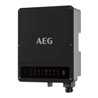
Describes the functions and indicators found on the front panel of the PV-Inverter.
Explains how the inverter optimizes power output from PV panels under varying conditions.
Discusses the accuracy limitations of the readings displayed on the inverter's LCD.
Details the messages and information displayed on the inverter's LCD for various operating conditions.
Provides details on model, contrast settings, firmware, and language options for the inverter.
Explains the meaning and status indicated by the green and red LEDs on the PV-Inverter.
Describes the RS232 port for monitoring and firmware upgrades, including pin definitions.
Discusses the expansion port for optional communication cards like RS485.
Details the procedure for updating the inverter's firmware using the RS232 port.
Provides troubleshooting steps for various system-level faults and error messages.
Lists common inverter failures and their corresponding troubleshooting actions and solutions.
Presents graphical data showing the inverter's efficiency performance under different load conditions.
Lists the EMC, grid interface, grid monitoring, and low voltage regulations the inverter complies with.
Provides information on filling out an incident report for client assistance services.
| Max. apparent AC power | 2000 VA |
|---|---|
| AC voltage range | 180-265 V |
| Nominal AC voltage | 230 V |
| Max. Input Current | 12 A |
| Number of MPP trackers | 1 |
| Power Factor | > 0.99 |
| THD | < 3 % |
| Cooling | Natural convection |
| Protection Degree | IP65 |
| Warranty | 5 years |
| Nominal AC Frequency | 50/60 Hz |
| Operating Temperature | -25°C to +60°C |