3
11/1/2016 - DOCUMENT NUMBER: 10-0309
© 2016 AEM Performance Electronics
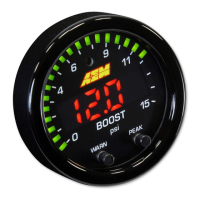
30-0309 - BOOST/FUEL PRESSURE 15PSI SAE ONLY
Operation
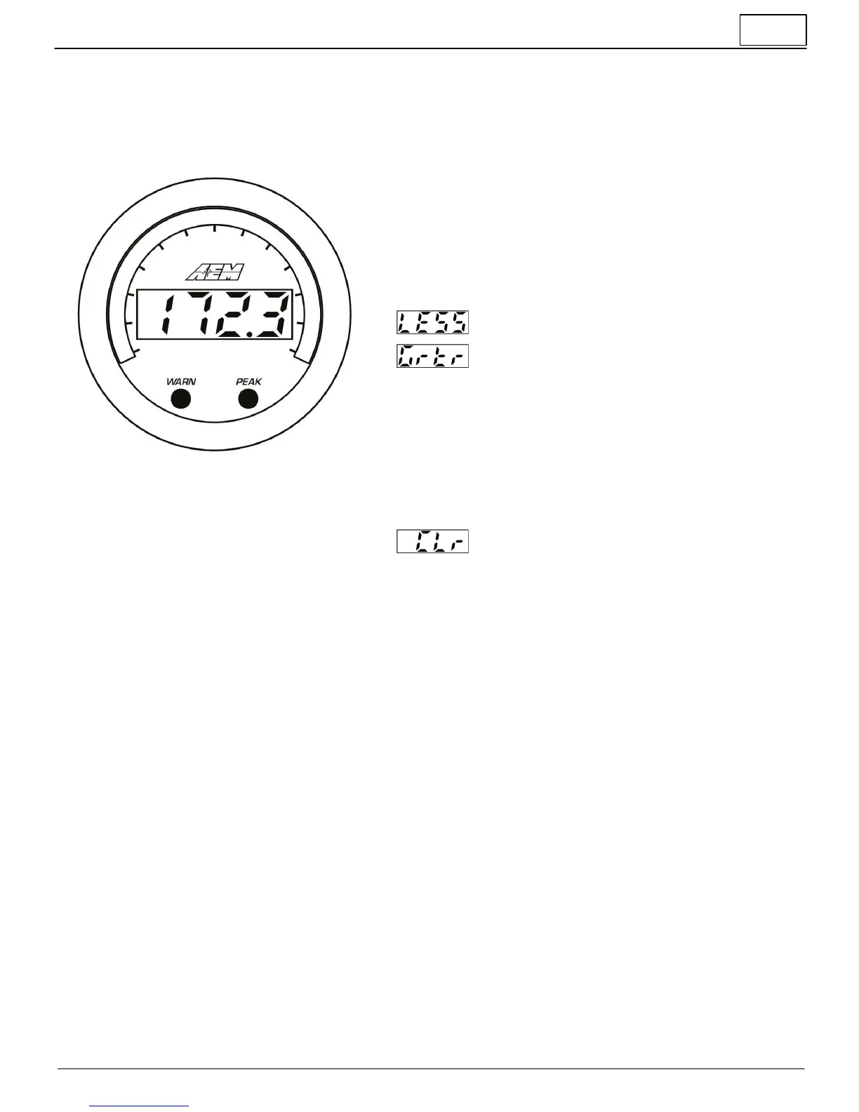
The inner numeric LEDs and outer ring LEDs display the currently measured sensor reading; the inner numeric LEDs will
flash when the sensor reading exceeds the (configurable) warn/alarm threshold value. WARN and PEAK buttons are
located on the face of the gauge and are used to perform the following functions.
Display or adjust warn/alarm threshold
§ Press the WARN button; the warn/alarm threshold will be displayed
and the outer LEDs will flash
§ Use either the WARN or PEAK buttons to decrement or increment
the threshold value
§ Depress and hold both the WARN and PEAK buttons until LESS or
GrTr appears
§ Press the WARN button to toggle between LESS and GrTr modes
Warn/alarm activated when sensor reading is less
than threshold value
Warn/alarm activated when sensor reading is greater
than threshold value
§ The gauge will return to normal display mode a few seconds after
the last button press
Display or clear stored peak value
§ Press the PEAK button; the peak (highest) sensor reading will be
displayed and the outer LEDs will flash
§ The peak value will be retained across power cycles
§ While the peak value is being displayed, depress and hold the
PEAK button for three seconds until "CLr" appears to clear the
peak value
Will be displayed to confirm the peak value has been
reset
§ The gauge will return to normal display mode shortly after the last
button press
Sensor Installation
§ Install sensor with a liquid thread sealant suitable for NPT fittings.
§ Remote mounting pressure sensors using flexible tubing and anti-vibration mounts will help extend sensor life.
§ Secure wiring to vehicle with wire ties paying special attention to the sensor harness routing beneath the vehicle and/
or in the engine compartment.
§ Take care when routing the sensor harness near hot exhaust components, use strain reliefs and wire coverings as
appropriate.
§ Use a 5A inline fuse on the switched 12V power supply line (Pin 1 - Power/IO).