Alarm and Processing Control: when the CO
2
concentration is higher than the set point and remains
constant for some time (to avoid false alarm for an abrupt increase of partial concentration), the CO
2
Concentration Indicator Lamp is flashing with the alarm. Start both the left fan and the right fan to
enhance ventilation inside and outside. If the CO2concentration remains unchanged, open the ICU
door to enhance ventilation. When the CO
2
concentration is equal to or lower than the set point, switch
off the CO
2
indicator lamp and close the alarm. If fans are not needed when other functions are working
the fans automatically stop.
CO
2
Concentration Control: the default factory setting is 1000PPM-1000 in a million (0.10%). PPM=so-
lute mass/solution mass*1000000. Reference set point: the CO
2
concentration of 0.1%is harmful to
animals; the CO
2
concentration of 0.5% causes loss of breath and dizziness; the CO
2
concentration of
1% makes it increasingly difficult for animals to breath, gradually fading to a fatal point.
CO
2
concentration in air: 0.030% -- 0.039% (oxygen concentration: 20.95%).
1. Disinfection & Sterilization: after incubation or caring of one pet finishes treatment and care, it is
suggested to disinfect and sterilize this machine. Do this once every week when not in use.
2. Separate cleaning of the Humidifier
If the Humidifier fails to produce moisture, or the water spills out, take the following measures:
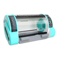
a) As shown in Figure 8.2.1-a,open the cover plate of the right Control Rack.
b) As shown in Figure 8.2.1-b and Figure 8.2.1-c,remove Water Level Sensors and Humidifier from the
Water Vessel. Take out the Water Vessel.
c) As shown in Figure 8.2.1-d, empty the Vessel. Brush off the mineral substance such as water scale
or verdigris on the Vessel, Water Level Sensors and Humidifier. If the filter of the Humidifier fails to
work, replace with a new filter.
d) Install Water Level Sensor and Humidifier, place the water vessel back and secure the cover plate.
Press "SET" key to remove disengage alarms. See fig. 7.11.1.
Sensor
of Vessel
Water Vessel
Figure 8.2.1-bFigure 8.2.1-a
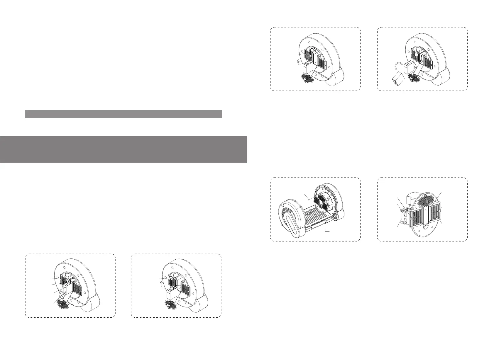
3. Complete Cleaning and Maintenance: remove and clean parts and assemblies periodically. Desired
results are achieved only by cleaning after removal.
Steps for Disassembling Components:
Remove four screws from the master control rack on the right to take down the right master control
rack, (remove the left master control rack in the same way). See fig. 8.3.1.
Remove power connection plugs on power cords on one side of the master control rack one by one.
Note that plugs have different colors for each electrical component.
Warning: do not remove control racks or electrical components from control racks immediately after
shut down; give it some time to cool down. The heaters in control racks reach high temperature.
Remove control racks or contact heaters after a 30 minutes respite after shutdown.
Remove four screws in the fan box and take out the whole heater. Clean the fan. Try not to remove heat
sinks from the fan, especially PTC heater bands that cannot be removed from heat sinks. See fig.
8.3.2.
Remove and clean filters behind the square plastic section inside the chamber.
Take out the humidifier. If it is working normally, it is not necessary to clean the humidifier. For separate
cleaning of the humidifier, it is not necessary to remove control racks. See the chapter of separate
cleaning of the humidifier above. If the humidifier is definitely damaged or does not work after separate
cleaning, remove the humidifier for cleaning and maintenance. (See fig. 8.3.3):
Sensor
Figure 8.3.1-b
Figure 8.3.1-a
Figure 8.2.1-c Figure 8.2.1-d
Temperature
Humidity sensor
PTC Heater
14 15
Cleaning and Maintenance
 Loading...