MAINTENANCE
6-5
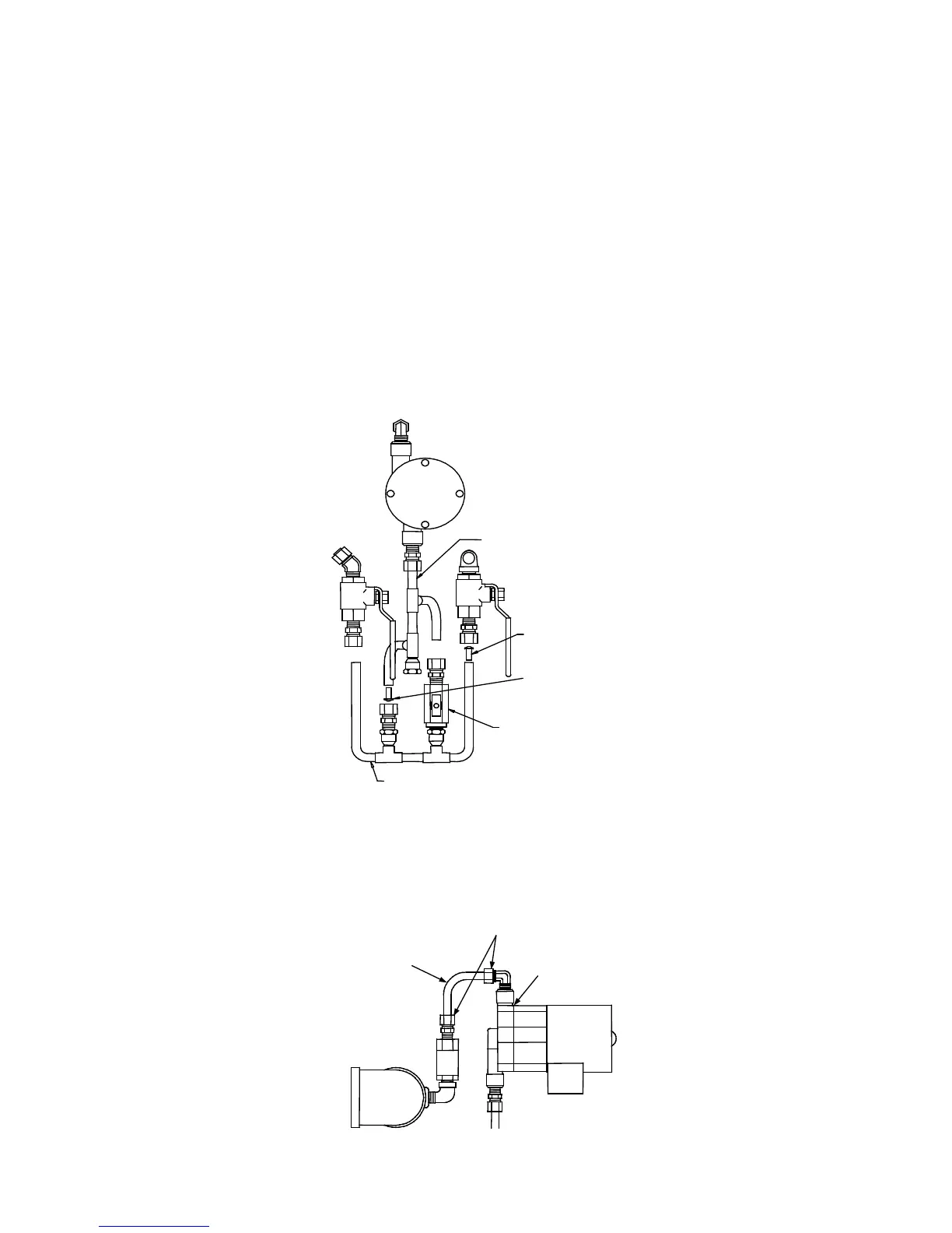
Figure 6.4
Compression Fitting Locations
10. Carefully remove the lower tubing assembly taking care not to lose either the cold water or hot water
mixing orifice, (See Fig. 6.5).
11. Loosen the compression fitting holding the hydraulic zero and control orifice tube assembly to the
pump’s impeller housing, (See Fig. 6.6).
NOTE:
The cold water mixing orifice (P/N GP-122401) is slightly larger than the hot water mixing orifice (P/N GP-
122760). Each orifice must be correctly installed for proper temperature control.
HYDRAULIC ZERO &
CONTROL ORIFICE
TUBING ASSEMBLY
COLD WATER
MIXING ORIFICE
HOT WATER
MIXING ORIFICE
HYDRAULIC ZERO
NEEDLE VALVE
LOWER TUBING ASSEMBLY
Figure 6.5
BTU Transmitter Disassembly
COMPRESSION
FITTINGS
IMPELLER
HOUSING
PUMP OUTLET
TUBE
 Loading...