INSTALLATION
2-3
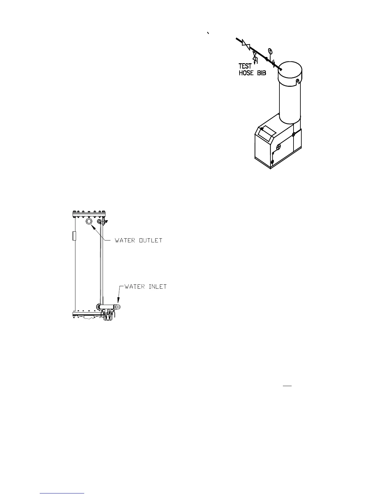
Shut-off valves and union conections must be
installed in the inlet and outlet lines for
maintenance. The use of dielectric unions is
recommended. Install the piping and acces-
sories as per the following drawings, located in
Appendix F of this manual.
• SD-A-705 for single units
• SD-A-706 for multiple units
• SD-A-707 for single units with a stratified
tank
• SD-A-708 for multiple units with a stratified
storage tank
• SD-A-709 for single units with a stratified
tank for 2 temperature zones
NOTE:
All piping must be arranged so that it does not
interfere with removal of any cover, inhibit
service or maintenance, or prevent access
between the unit and walls, or another unit.
Figure 2.3
Inlet and Outlet Location
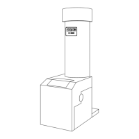
2.3.3 TEST HOSE BIB
A Test Hose Bib connection, upstream of the
shut off valve on the hot water outlet, is required
for startup and testing (Figure 2.4). It should be
a minimum of 3/4". The Test Hose Bib cannot
be omitted.
Figure 2.4
Hose Bib Location
NOTE:
The maximum working pressure for installations
within the Province of Alberta is 87 psig.
Therefore, a pressure & temperature relief valve
with a setting of 75 psig/210°F is supplied with
Alberta shipments. See Drawing AP-A-863 in
Appendix E.
2.3.4 PRESSURE/TEMPERATURE
RELIEF & DRAIN
VALVE INSTALLATION
An ASME rated Pressure/Temperature Relief
Valve is supplied with each unit. With the
exception of Alberta installations (see above
Note), the valve setpoint is 150 psig/210°F.
Install the relief valve as shown in Figure 2.5. A
suitable pipe compound should be used on the
threaded connections. Any excess should be
wiped off to avoid getting any into the valve
body. The relief valve should be pipied to within
12 inches of the floor to prevent injury in the
event of a discharge. The relief piping must be
full size, 1-1/2”, without reduction. No valves,
restrictions, or other blockages are allowed in
the discharge line. In multiple unit installations
the discharge lines must not
be manifolded
together. Each must be individually run to a
suitable discharge location.
 Loading...