INSTALLATION
2-6
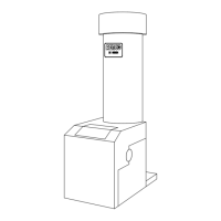
2.4.2 MANUAL GAS SHUTOFF VALVE
A 1-1/4” manual gas shutoff valve is furnished
with each unit and should be positioned as
shown in Figure 2.7. The valve must be installed
upstream of the gas supply regulator in a readily
accessible location.
2.4.3 IRI GAS TRAIN KIT
The IRI gas train is an optional gas train
required in some areas by code or for insurance
purposes. The IRI gas train comes pre-
assembled and wired from the factory. See
Appendix E, Drawing SD-A-661.
The IRI gas train may be ordered pre-assembled
or as separate components. If either IRI gas
train option is ordered a complete instructional
package, detailing field installation will be
included. To obtain a copy of an IRI instructional
package prior to the equipment shipping, contact
your local representative or AERCO.
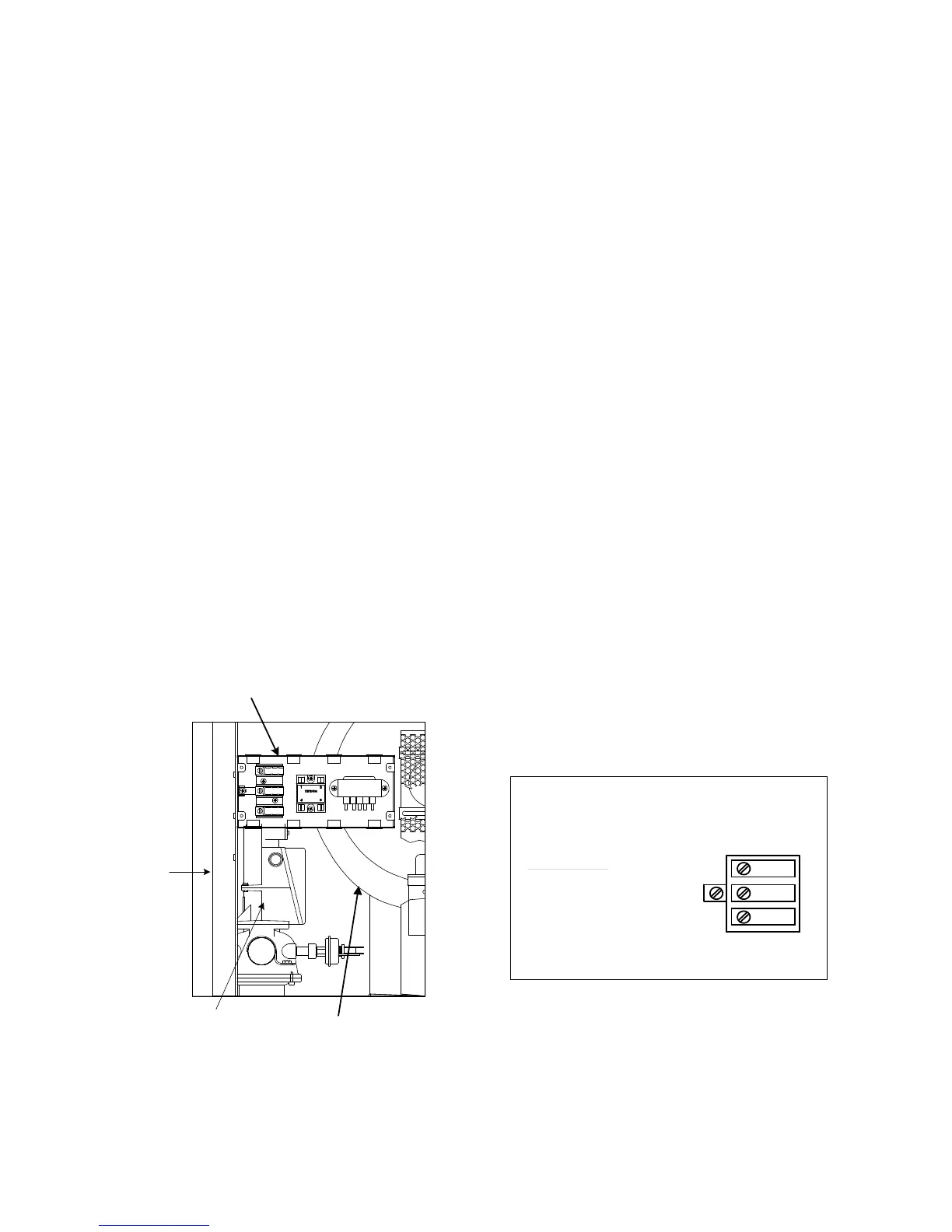
2.5 ELECTRICAL SUPPLY
The AERCO Gas Fired Equipment Electrical
Power Wiring Guide, (GF-1060), must be
consulted in addition to the following material
before wiring to the unit is started. AC power
connection to the unit are made at the Power
Box.This box is located on the front right side of
the unit as shown in Figure 2.8.
POWER BOX
BLOWER
SSOV
ACTUATOR
FRAME
Figure 2.8
AC Power Box Location
NOTE:
All electrical conduit and hardware should be
installed so that it does not interfere with the
removal of any cover, inhibit service or
maintenance, or prevent access between the
unit and walls or another unit.
2.5.1 ELECTRICAL REQUIREMENTS
Electrical requirements for each unit are 120
VAC, 1 Phase, 60 Hz, 20 Amps from a
dedicated electrical circuit. No other devices
should be on the same electrical circuit as a
KC1000 unit.
A double-pole switch must be installed on the
electrical supply line in an easily accessible
location to quickly and safely disconnect
electrical service. DO NOT attach the switch to
sheet metal enclosures of the unit.
After placing the boiler in service, the ignition
safety shutoff device must be tested. If an
external electrical power source is used, the
installed boiler must be electrically bonded to
ground in accordance with the requirements of
the authority having jurisdiction. In the absence
of such requirements, the installation shall
conform to National Electrical Code (NEC),
ANSI/NFPA 70 and/or the Canadian Electrical
Code (CEC) Part I, CSA C22.1 Electrical Code.
The electrical wiring diagram is shown in Figure
2.9. Conduit should be run from the knockouts in
the side of the box in such a manner that it does
not interfere with the removal of any sheet metal
covers. A flexible electrical connection may be
utilized to allow the covers to be easily removed.
USE COPPER CONDUCTORS ONLY FOR FIELD WIRING
60 HZ
DISCONNECT POWER BEFORE SERVICING
DANGER: HIGH VOLTAGE
20 AMP
120 VAC,
NEUTRAL
GROUND
LINE
POWER BOX
AERCO INTERNATIONAL INC.
INPUT POWER
Figure 2.9
AC Power Wiring Diagram
2.6 FIELD CONTROL WIRING
Each unit is fully wired from the factory with an
internal operating control system. No field
control wiring is required for normal operation.
However, the KC1000 control system does allow
for some control and monitoring features.
 Loading...