MAINTENANCE
6-9
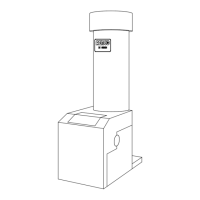
Figure 6.12
Exhaust Sensor Connector Location
13. Disconnect the air/fuel valve wiring harness connector from the control panel.
14. Disconnect wires #24 and #17 from the blower proof switch (See Fig. 6.13).
TO FRAME
HARNESS
BLOWER PROOF
SWITCH
AIR/FUEL VALVE
Figure 6.13
Blower Proof Switch Wire Location
(older style switch shown at left, newer style at right)
15. Loosen the hose clamp on the air/fuel valve inlet and slide the clamp back towards the blower, (See
Fig. 6.14).
Harness
 Loading...