Do you have a question about the AERMEC 2802 and is the answer not in the manual?
Instructions on maintaining and handling technical documentation for proper use.
Essential safety measures and guidelines for unit installation and operation.
Overview of available cooling-only unit configurations and temperature limits.
Details on the variety of NS series chiller sizes and configuration options.
Guide for selecting the appropriate unit based on model codes and specifications.
Detailed description of the chiller's internal components like compressors and heat exchangers.
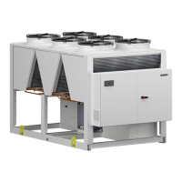
Information on the unit's structural frame and fan assembly specifications.
Overview of essential hydraulic parts such as pumps and expansion tanks.
Details on safety devices and control elements for unit operation.
Description of the electrical panel, switches, and control interfaces.
Explanation of the unit's electronic control system and its features.
Description of accessories related to electrical regulation and communication.
Details on electrical accessories like phase advancers and noise reduction kits.
Overview of general accessories for protection and vibration isolation.
Comprehensive technical specifications for NS chillers, models 1251 through 1802.
Detailed technical specifications for NS chillers, models 2002 through 3402.
Comprehensive technical data for NS chillers, models 3602 through 5702.
Technical specifications for NS chillers, models 6003 through 7203.
Graphical representation of operating limits for «° and L» versions.
Operating limits graphs for «A and E» versions, specifically for models 5402-5702.
Key design parameters including maximum allowable pressures and temperatures.
Graphical display of operating limits for «A and E» versions.
Factors for adjusting cooling capacity and input power in standard versions.
Correction factors for standard units in silenced versions.
Correction factors for high-efficiency versions, excluding specific sizes.
Correction factors for high-efficiency, silenced versions, excluding specific sizes.
Correction factors for high-efficiency versions, specifically for sizes 5402 and 5702.
Correction factors for high-efficiency, silenced units, excluding specific sizes.
Factors to adjust performance for water temperature differences other than the rated value.
Factors to account for heat exchanger fouling in performance calculations.
Guide on interpreting graphs to determine glycol percentage and correction factors.
Recommended minimum water volumes for various unit sizes to ensure proper operation.
Information on pressure drops associated with the desuperheater circuit.
Factors to adjust desuperheater performance for non-nominal water temperatures.
Pressure drop data for units equipped with total heat recovery systems.
Pressure drop values for total recovery systems at different water temperatures.
Factors for adjusting total recovery performance based on water temperature.
Guidelines and charts for selecting appropriate pumps based on unit model and flow rate.
Sound level data for standard NS units at full load across various octave bands.
Sound levels for silenced NS units («L» version) at full load across octave bands.
Sound data for high-efficiency NS units («А» version) at full load.
Sound levels for high-efficiency, silenced NS units («E» version) at full load.
Sound data for NS units with the AK accessory for enhanced noise reduction.
Required minimum clearances around the unit for installation and maintenance.
Dimensional details for units with 3780 mm carpentry, including various models.
Dimensional information for units featuring 4770 mm carpentry configurations.
Dimensional data for units with 7160 mm carpentry, covering standard and two-circuit models.
Dimensional tables for units with 10120 mm carpentry, including various models.
Dimensional specifications for units with 11100 mm carpentry configurations.
Dimensional data for units with 12520 mm carpentry.
Dimensional information for units with 13510 mm carpentry.
Advice on selecting and installing external components for the hydraulic circuit.
Steps for loading and checking the hydraulic system pressure, including glycol considerations.
Procedure for safely emptying the hydraulic system, including environmental warnings.
Guidelines on selecting appropriate electric cable sizes for safe installation.
Instructions for safely connecting the unit to the electrical power supply.
Specifics on power connection for different unit configurations and network wiring.
Information on optional auxiliary electrical connections for the user or installer.
Electrical data specifications for units with «°/L» versions.
Electrical data details for units featuring «A/E» versions.
Pre-start checks and requirements before initial machine commissioning.
Step-by-step guide for the initial startup sequence of the unit.
Procedures for seasonal adjustments and checks on the unit's operational parameters.
Definition of the default cooling set point and temperature difference (Δt).
Explanation of functions that manage compressor start intervals to prevent damage.
How the electronic board manages the circulation pump and flow rate alarm.
Details on the anti-freeze alarm system and its protective functions.
Explanation of the water flow rate alarm and its impact on compressor and pump operation.
Periodic checks for the hydraulic circuit, including filling, filters, and pressure.
Routine inspections for the electric circuit, focusing on safety, supply, and connections.
Essential checks for the chiller circuit, including compressors, pressure, and switches.
Inspection of mechanical components like screws and paneling for proper tightening and condition.
Step-by-step guide for loading refrigerant, including safety and environmental precautions.