69
IFCLTY 1112 - 4528511_04
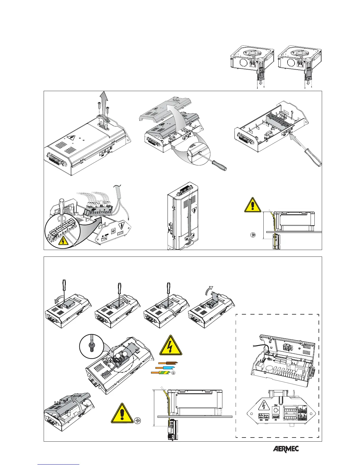
ELECTRIC CONNECTIONS
The unit must be connected directly
to an electrical outlet or to an
independent circuit.
The FCL cassette fan coils must be
powered with 230V ~ 50Hz current
and have an earth connection. The
line voltage must remain within the
tolerance of ±10% with respect to the
nominal value.
In order to protect the unit against short
circuits, mount a max. 2A 250V (IG)
magnet circuit breaker omnipolar
switch on the power supply line with
a minimum contact opening distance
of 3 mm.
The electrical power supply cable must
be of the H07 V-K or N07 V-K type with
450/750V insulation if inside a tube
or raceway. Use cables with double
H5VV-F type insulation for visible
cable installation.
Refer to the wiring diagrams of the
appliance and the control panel.
230VAC
- L - N
> 650mm
230VAC
GLL10
GLL20
- L - N
> 650mm
230VAC
L
N
230VAC
L
N
VMF-SW1
CN3
GLL10M - GLL10R - GLL20R - GLL10N - GLL20N
GLL10N - GLL20N