12
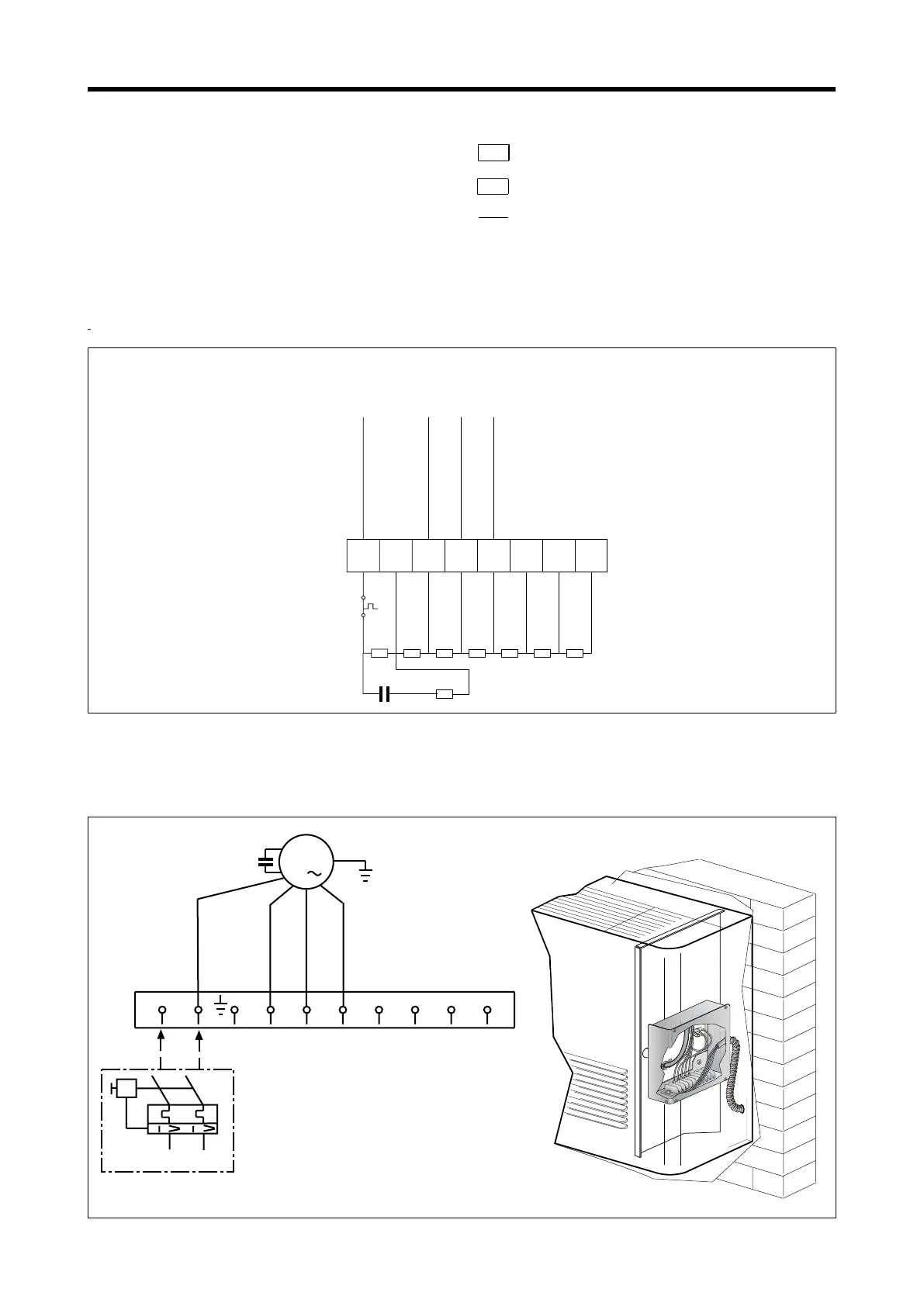
CRE = Electric heater contactor
Contacteur résistance eléctrique
IG = Magnetothermic switch
Disjoncteur magnétothermique
M = Terminal board • Boitier
MV = Fan motor • Moteur ventilateur
RE = Electric heater • Résistance électrique
TSRM = Manual resetting thermostat
Thermostat à réarmement manuel
Components not supplied
Composants non fournis
Optional components
Composants en option
On-site wiring
Raccordements à effectuer in situ
BL = Blue • Bleu
MA = Brown • Marron
NE = Black • Noir
RO = Red • Rouge
WIRING DIAGRAMS •
READING KEY
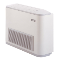
universal: vertical wall or horizontal wall installation. no controls
universelle: installation verticale sur paroi ou horizontale sur plafond. sans commandes
FCX - USPO MOTOR CONNECTION DIAGRAM SCHEMA DE RACCORDEMENT MOTEUR FCX - USPO
Power Supply