EN FR
8 FCZI EUP 1906 _4033745_00
PRODUCT DESCRIPTION
• The units are shipped in cardboard box standard packing and polystirene
shells.
PACKING
WARNING: The fancoil is connected to the power supply and a water
circuit. Operations performed by persons without the required technical
skills can lead to personal injury to the operator or damage to the unit
and surrounding objects.
POWER THE FANCOIL WITH SINGLEPHASE 230 V ONLY
• Use of other power supplies could cause permanent damage to the fancoil.
NEVER USE THE FANCOIL FOR APPLICATIONS FOR WHICH IT WAS NOT
DESIGNED
• Do not use the fancoil in husbandry applications (e.g. incubation).
AIR THE ROOM
• Periodically air the room in which the fancoil has been installed; this is
particularly important if the room is occupied by many people, or if gas
appliances or sources of odours are present.
CORRECTLY ADJUST THE TEMPERATURE
• Room temperature should be regulated to ensure maximum comfort to
persons present, particularly in the case of the elderly, infants and invalids.
Prevent temperature uctuations between indoors and outdoors greater
than 7 °C during summer.
• Note that very low temperatures during summer will lead to greater electricity
consumption.
ORIENT AIR FLOW CORRECTLY
• Air delivered by the fancoil should not be oriented directly at people; even
if air temperature is greater than room temperature, it can cause a cold
sensation and consequently discomfort.
DO NOT USE HOT WATER
• When cleaning the indoor unit, use rags or soft sponges soaked in warm
water (no higher than 40°C).
• Do not use chemical products or solvents to clean any part of the fancoil.
• Do not splash water on interior or exterior surfaces of the fancoil; danger of
short circuit.
PERIODICALLY CLEAN THE FILTER
• Frequent cleaning of the lter will ensure more ecient unit operation.
• Check whether the lter requires cleaning; if it is particularly dirty, clean it
more often.
• Clean the lter frequently. Use a vacuum cleaner to remove built up dust.
Avoid water or detergents if possible since they greatly accelerate loss of the
lter's electrostatic charge.
• After cleaning and drying the lter, t it on the fancoil by following the
removal procedure in reverse order.
SPECIAL CLEANING
• The removable drip tray and fan volute ensure thorough cleaning of the
unit (by specically trained personnel), essential for installations in venues
subject to crowding or in those with special hygiene requirements (chapter
"drawings - Figure 1").
DURING UNIT OPERATION
• Always leave the lter on the fancoil during operation (otherwise dust in the
air could soil the surface of the coil).
IT IS NORMAL
• During cooling, water vapour may be present in the air delivery of the fan coil.
• In the heating function it might be possible to hear a slight hiss around the
fan coil. Sometimes the fan coil might give o unpleasant smells due to the
accumulation of dirt in the air of the environment (especially if the room is not
ventilated regularly, clean the lter more often).
• During the operation, there could be noises and creaks inside the device, due
to the various heat expansions of the elements (plastic and metallic), but this
does not indicate any malfunctioning and does not cause damage to the unit
unless the maximum input water temperature is exceeded.
WARNING
• Avoid that the device is used by children or incompetent persons without
appropriate supervision; also note that the unit should not be used by
children as a game.
IMPORTANT MAINTENANCE INFORMATION
• Brushless motor with 0-100% speed continuous variation to guar-
antee best performance at very low sound level
• Low loss of charge in the heat exchanger
• Easy installation and maintenance
• Air felter G2 for all versions.
• Extractable shrouds for easy, effective cleaning
• Water connections can be reversed during installation phase
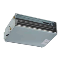
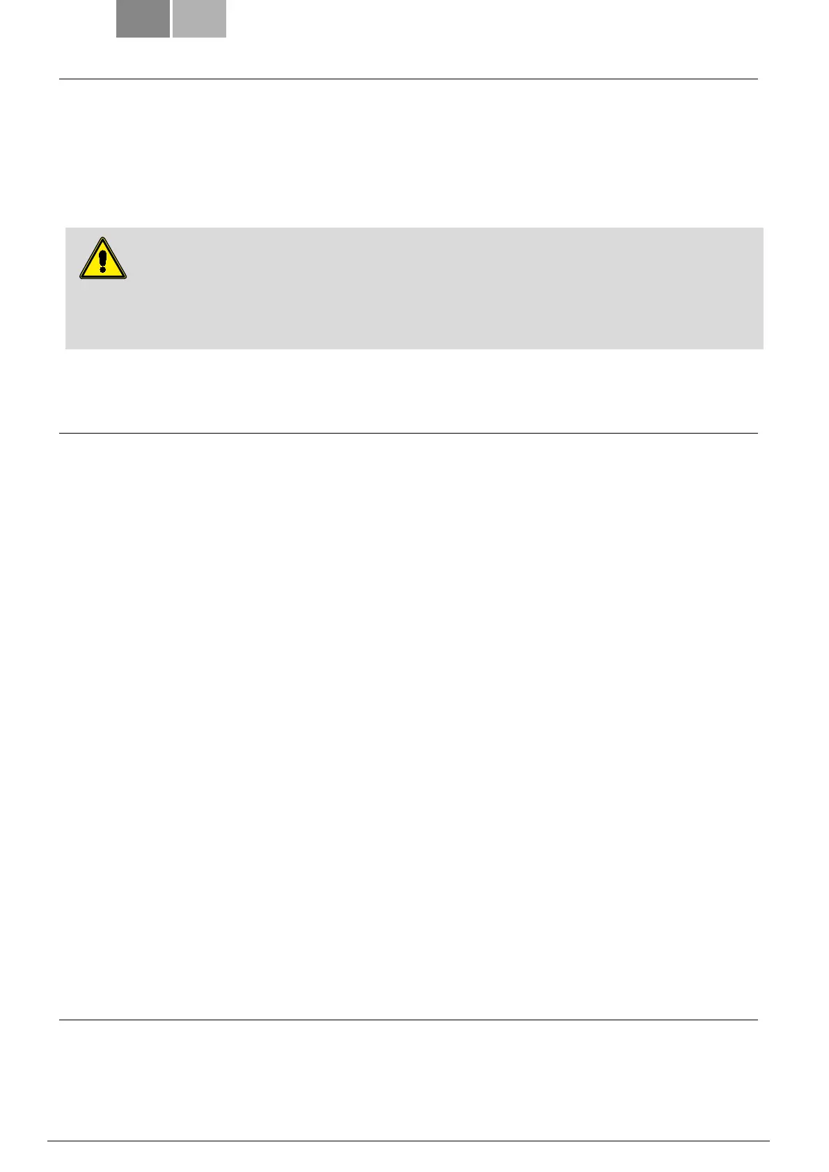
• FCZI_EUP
- wall/ceiling mounted without cabinet
Vertical or horizontal installation
- For 2/4 pipe system
ATTENTION
Electrical diagrams, installation and operating instructions for accessories and thermostats are supplied
together with the accessory itself. For more information contact Aermec.
MALFUNCTION
WARNING: In the event of a malfunction refer to the Table of Alarm Codes to interpret the signals from the two
LEDs (Alarm / Power) which indicate the operating status of the unit. The inverter wiring diagram is located
within the unit.