7
CARATTERISTICHE
•
FEATURES
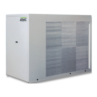
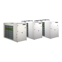
DESCRIZIONE DEI COMPONENTI
1 SCAMBIATORE LATO ARIA
È realizzato con tubi di rame ed alette in alluminio bloccate
mediante espansione meccanica dei tubi.
È del tipo ad alta efficienza (alette intagliate).
2 COMPRESSORE
Di tipo ermetico alternativo o scroll a seconda dei modelli,
è dotato di cuffia fono-isolante ed il vano compressori è iso-
lato acusticamente.
3 FILTRO DEIDRATATORE
Di tipo meccanico realizzato in ceramica e materiale igro-
scopico, è in grado di trattenere le impurità e le eventuali
tracce di umidità presenti nel circuito frigorifero.
4 PRESSOSTATO DI ALTA
A taratura fissa, posto sul lato ad alta pressione del circuito
frigorifero, arresta il funzionamento del compressore in caso
di pressioni anomale di lavoro.
5 SPIA DEL LIQUIDO
Serve per verificare la carica di gas frigorigeno e l’eventuale
presenza di umidità nel circuito frigorifero.
6 QUADRO ELETTRICO
Contiene la sezione di potenza e la gestione dei controlli e
delle sicurezze.
È conforme alle norme EN 60204-1, EN 60335-2-40, IEC
801-4 livello 3.
7 STRUTTURA PORTANTE
Realizzata in lamiera di acciaio zincata a caldo, di adegua-
to spessore, è verniciata con polveri epossidiche per garan-
tire la resistenza agli agenti atmosferici.
8 GRUPPI VENTILANTI
Di tipo elicoidale, bilanciati staticamente e dinamicamente,
sono direttamente calettati sull’albero del motore.
Gli elettroventilatori sono protetti con interruttori magneto-
termici e con griglie metalliche fissate sulla parte superiore
della carpenteria.
- RUBINETTO LIQUIDO
Consente di intercettare il gas refrigerante in caso di manu-
tenzione straordinaria.
- PRESSOSTATO DI BASSA
A taratura fissa, posto sul lato a bassa pressione del circuito
frigorifero, arresta il funzionamento del compressore in caso
di pressioni anomale di lavoro.
- SILENZIATORE
Posto sulla mandata del compressore, serve ad attenuare le
pulsazioni causate dal moto del gas.
Non è presente se il compressore è di tipo Scroll.
ORGANI DI SICUREZZA E REGOLAZIONE
- Sistema di interblocco porta.
- Magnetotermico protezione compressori.
- Magnetotermico protezione ventilatori.
- Magnetotermico protezione ausiliario.
- Contattori alimentazione compressori.
- Contattori alimentazione ventilatori.
- Resistenza carter compressori (escluso NRA 352 C - 3527
C - 201 C - 251 C).
- Pressostati di bassa e alta pressione.
- È inoltre possibile portare a distanza i seguenti comandi e
segnalazioni:
interruttore acceso/spento;
pulsante di avviamento;
lampade per la segnalazione del blocco;
lampade per la segnalazione del funzionamento;
l’ingresso per il consenso di funzionamento.
Fare riferimento agli schemi elettrici a bordo macchina.
COMPONENT DESCRIPTION
1 AIR SIDE EXCHANGER
Made of aluminium fins mechanically bonded to copper
pipes.
High efficiency coil (slotted fins).
2 COMPRESSOR
Hermetic compressors either reciprocating or scroll depen-
ding on the models, all the compressors are fitted with an
acoustic jacket. The compressor housing is soundproofed.
3 FILTER DRYER
A mechanical filter in ceramic and hygroscopic material,
capable of retaining the impurities and any traces of humi-
dity present in the refrigerant circuit.
4 HIGH PRESSURE SWITCH
With a fixed calibration, mounted on the high pressure side
of the refrigerant circuit, it blocks operation of the compres-
sor in the event of abnormal working pressures.
5 SIGHT GLASS
Checks refrigerant gas charge status and for presence of
moisture in the cooling circuit.
6 SWITCHBOARD
It contains the power section and the management of the
controls and safeties. It has conform to EN 60204-1, EN
60335-2-40, IEC 801-4 level 3.
7 CHANNEL FRAME
Made of hot galvanised steel sheet, of substantial thickness,
it is painted with epoxy powder to guarantee a long-term
weather resistance.
8 FAN GROUP
Propeller fans, statically and dynamically balanced, they are
directly coupled to the motor shaft.
The fans are protected by a circuit breaker and metal guard
fixed to the top of the housing.
- LIQUID CUT-OFF VALVE
It permits the refrigerant flow to be cut-off during repair
work.
- LOW PRESSURE SWITCH
With fixed calibration, it is mounted on the low pressure
side of the refrigerant circuit, it blocks the compressor in the
event of abnormal working pressures.
- MUFFLER
Installed on compressor delivery line, the silencer dampens
pulsations caused by gas movement.
Not present on Scroll type compressors.
SAFETY AND CONTROL DEVICES
- safety door interlock system.
- compressor circuit breaker.
- fan circuit breaker.
- auxiliary circuit breaker.
- compressor starters.
- fan starters.
- compressor crankcase heater (excluding NRA 352 C - 3527
C - 201 C - 251 C).
- low and high pressure switches.
- It is also possible to remote the following commands and
signals:
the on/off switch,
the start button
the alarm block signal light,
the working signal light
the operating consensus input
Refer to the wiring diagrams on the machine.
 Loading...