21
• Open the external covering panels (if present)
• Make sure that the switch is at “OFF” before opening the electric
control board for the connection of the unit to the power supply.
• Use the plates/holes to pass the main electric power supply
cable and the cables of the other external connections under the
responsibility of the installer.
• It is prohibited to access positions not specically envisioned in this
manual with electric cables.
• Avoid direct contact with non-insulated copper piping and with the
compressor.
• Identify the clamps for the electric connection and always refer
exclusively to the wiring diagram supplied with the unit.
• Remove any protections from the cable xing points..
• For the functional connection of the unit, take the power supply
cable to the electric control board inside the unit and connect it to
clamps. L1-L2-L3, N (if present), and PE respecting the polarities L1-
L2-L3 and N as phases, and PE as grounding
• Ensure that all protections removed for the electric connection have
been restored before powering the unit electrically.
• Close all the opened panels.
• Turn the switch at “ON” position.
• Position the system master switch (outside the appliance) at “ON”.
For auxiliary connection please refer to the wiring diagrams supplied
with the unit,
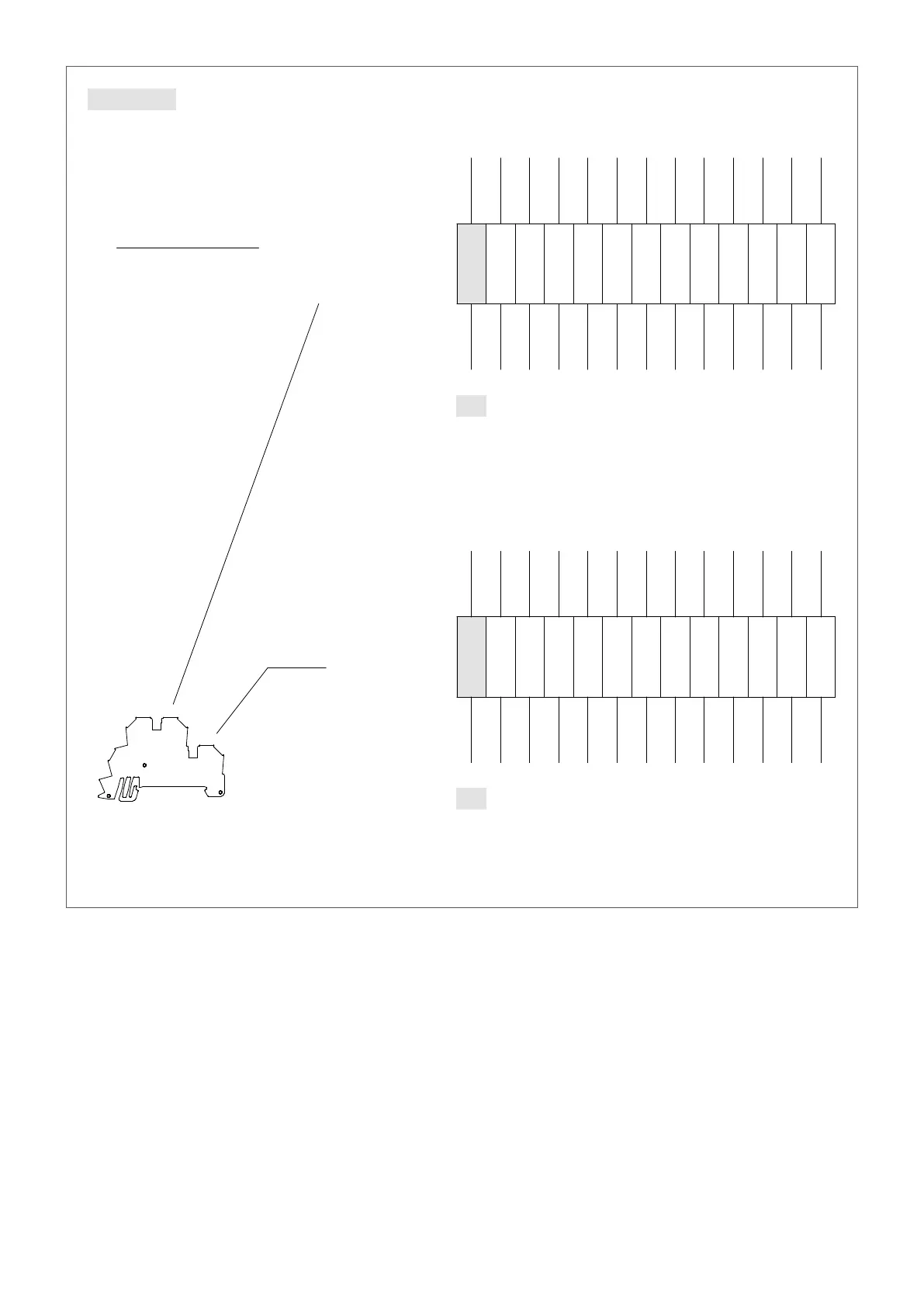
ELECTRIC POWER CONNECTION TO THE ELECTRICAL MAINS
ELECTRIC POWER CONNECTION TO THE ELECTRICAL MAINS
2
B
F
A
3
31/03/2017
4
RIEPILOGO MORSETTI
5
E
C
D
1
31/03/2017
1 2
76
5 6 7 8
8
C
D
B
DI
NOME FILE:
TIPICO:
SUBITI. E' FATTA RISERVA DI TUTTI I DIRITTI DERIVANTI DA BREVETTI O MODELLI
AUTORIZZAZIONE ESPLICITA. OGNI INFRAZIONE COMPORTA IL RISARCIMENTO DEI DANNI
NE' UTILIZZARE IL CONTENUTO O RENDERLO COMUNQUE NOTO A TERZI SENZA LA NOSTRA
NON E' PERMESSO CONSEGNARE A TERZI O RIPRODURRE QUESTO DOCUMENTO
QENRB3000_380026.sch
Zambiase Michele
REV. MODIFICA DATA
VERIFICATO
PROGETTO:
TERMINAL BOARD SUMMARY
=
+
FOGL.
DATA
DISEGN.
APPROV.
BEVILACQUA (VERONA) ITALY
AERMEC S.P.A.
3 4
E
DATA
NRB3000X°°A°°7BJ
A
DISEGNATO
F
42
28
7
QENRB3000_380026
De Togni
TERMINAL BOARD
MORSETTIERA QUADRO
X12
10
37
162
BK4
14.714.6
8
35
160
BK4
15.2
14
45
14.7
12
166
BK4
15.4
18
49
16
47
164
BK4
15.3
22
54
16.3
20
51
168
BK4
15.6
26
56
16.5
24
55
16.5
14.5
BK3
157
32
5
14.3
24
3
156
23
2
14.2 14.3
4 6
33
158
BK4
14.5
14.2
1
22
155
16.5
22
23
16.5
22
25
15.6
BK3
167
50
19
16.3
22
21
15.3
BK3
163
15
46
15.4
17
48
165
BK3
14.7
11
38
15.2
13
22
7
34
159
BK3
14.6
9
36
161
BK3
14.7
USCENTE
COLORE FILO
ENTRANT
COLOR WIRE
ENTRANTE
COLORE FILO
CLAMP
NR.
OUTLET
N° WIRE
REFERENCE
CROSS
COMPONENT
NR.
ENTRANT
N° WIRE
ENTRANTE
N° FILO
COMPONENTE
NR.
PAGINA
RIF.
USCENTE
N° FILO
MORSETTO
NR.
OUTLET
COLOR WIRE
USCENTE
COLORE FILO
ENTRANT
COLOR WIRE
ENTRANTE
COLORE FILO
CLAMP
NR.
OUTLET
N° WIRE
REFERENCE
CROSS
COMPONENT
NR.
ENTRANT
N° WIRE
ENTRANTE
N° FILO
COMPONENTE
NR.
PAGINA
RIF.
USCENTE
N° FILO
MORSETTO
NR.
OUTLET
COLOR WIRE
MP1C
MP1B
2° SET
X12.11
MP2B
MP2A
MP2C
EMF
0/1
MP1A
FL
X12.3
MP1A
FL
0/1
EMF
MP2C
MP2A
MP2B
2° SET
MP1B
MP1C
g. 1