17. M
EASUREMENTS OF THE CHILLERS LINES VERSIONS (C)
COOLING LINES
Model
Line length
[m]
Suction line f [mm] Liquid line f [mm]
Refrigerant
R410A per
metre of line
[g/m]
Refrigerant
R410A per
metre of line
[g/m]
C1/C3 C2/C4 C1/C3 C2/C4 C1/C3 C2/C4
NRL 2800C
0-10 54 67(*) 35 35 831 868
10-20 54 67(*) 35 35 831 868
20-30 54 67(*) 35 35 831 868
NRL 3000C
0-10 67(*) 67(*) 35 35 868 868
10-20 67(*) 67(*) 35 35 868 868
20-30 67(*) 67(*) 35 35 868 868
NRL 3300C
0-10 67(*) 67(*) 35 42 868 1237
10-20 67(*) 67(*) 35 42 868 1237
20-30 67(*) 67(*) 35 42 868 1237
NRL 3600C
0-10 67(*) 67(*) 42 42 1237 1237
10-20 67(*) 67(*) 42 42 1237 1237
20-30 67(*) 67(*) 42 42 1237 1237
Key
C1 = Chiller circuit 1
C2 = Chiller circuit 2
C3 = Chiller circuit 3
C4 = Chiller circuit 4
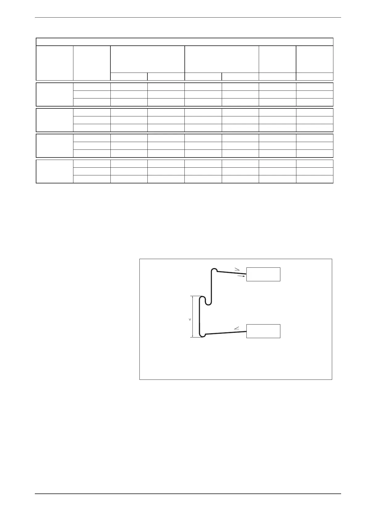
If the evaporator is positioned lower
than the condenser, drain-taps must be
available on the suction line to draw the
oil towards the compressor.
By "line length" we mean the distance
between the units, measured on the
liquid line. For further information,
contact the head office.
UNITÀ CONDENSANTE
0,5%
4m
0,5%
CONDENSING UNIT
UNITES DE CONDENSATION
KONDENSATOREINHEITEN
EVAPORATORE
EVAPORATOR
EVAPORATEUR
VERDAMPFER
(*) Parzializzazione minima 2 compressori ON
29
INRLPY. 02.10 4086916_01