55
Alarms summary table
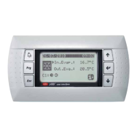
The units envision the signalling of the
possible unit malfunctions. These sig-
nals are indicated by the fl ashing alarm
key (bell) on the left part of the display. If
the bell is pressed again it allows to dis-
play the alarm in progress. The rearm of
these alarms can take place automati-
play is cancelled). The following table
lists the possible errors that the unit can
generate, and a brief explanation of the
possible causes.
cally, manually or semi-automatically
(on the basis of the type and serious-
ness of the alarm that has occurred). To
reset the alarm message, the bell key
must be pressed again (remember that
resetting the alarm does not solve the
cause that generated it, but just the dis-
Alarms rearm mode:
Manual rearm mode:
The unit is re-started manually by removing and re-applying the voltage.
Automatic rearm mode:
The unit is re-started automatically.
Semi-automatic rearm mode:
The unit is re-started automatically if the alarm repeats a maximum of three times consecutively, after which any
new alarm blocks the unit and makes manual rearm necessary.
ALARMS summary table
Alarm code Rearm Description
ALG01 Clock board broken or not connected
ALG02 Memory expansion damaged
ALR03 Serious alarm from digital input
ALO04 Slave off-line
ALA05 High pressure probe circuit 1 broken or not connected
ALA06 High pressure probe circuit 2 broken or not connected
ALA07 High pressure probe circuit 3 broken or not connected
ALA08 High pressure probe circuit 4 broken or not connected
ALA09 Low pressure probe circuit 1 broken or not connected
ALA10 Low pressure probe circuit 2 broken or not connected