Do you have a question about the AERMEC NXW and is the answer not in the manual?
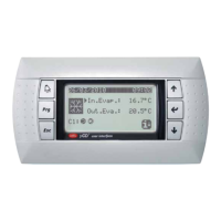
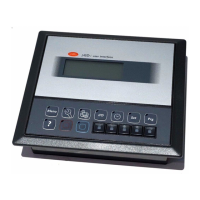
Describes navigation and operation buttons on the control panel.
Explains symbols used in the main menu for unit status indication.
Fundamental information regarding the unit's use.
Information on the cooling circuit and unit compressors.
Commands for switching the unit on and off.
Parameters for setting the unit's work set points.
Parameters for selecting the unit's functioning modes.
Parameters for setting timer periods for operation.
Parameters linked to the management of inputs and outputs.
List of alarms occurring on the unit, ordered by date.
Sub-menus for technical support and system information.
Password protected menu for authorized installers only.
Procedure for navigating between different menus on the control panel.
How to select and change parameter values within the unit's interface.
Describes the elements displayed on the unit's main screen.
Explains the meaning of displayed parameters and icons in the main menu.
Displays data related to the cooling circuit, like pressures and temperatures.
Shows general unit settings and parameters for regulation.
Controls the unit's power state directly from the PGD1 panel.
Manages unit power control via digital input or external supervisor.
Shows the currently active work set point for the unit.
Configures target temperatures for the cooling operation mode.
Configures target temperatures for the heating operation mode.
Selects the operational mode of the unit (cooling or heating).
Configures seasonal changeover command via digital input.
Configures the current date and time for the system.
Defines timed operational periods for daily use.
Defines time-based operation overrides for specific date ranges.
Configures unique operational settings for specific calendar days.
Displays pressure readings from the cooling circuit 1.
Shows water temperatures at the evaporator inlet and outlet.
Displays water temperature at the condenser outlet.
Displays pressure readings from the cooling circuit 2.
Shows water temperature at the condenser inlet.
Monitors pressure switch states for circuit 1.
Controls unit functions via external digital signals.
Monitors flow switch status for compressors.
Status of compressor 2 circuit breaker and phase control.
Monitors pressure switch states for circuit 2.
Status of compressor 2 circuit breaker.
Monitors flow switch status for evaporator pumps.
Monitors flow switch status for condenser pumps.
Monitors flow switch status for the condenser.
Shows ON/OFF status of circuit 1 compressors.
Shows ON/OFF status of circuit 2 compressors.
Shows ON/OFF status of condenser pumps.
Digital outputs for anti-freeze and compressor phase alarms.
Shows ON/OFF status of evaporator pumps.
Shows ON/OFF status of solenoid valves.
Shows ON/OFF status of 4-way valves.
Displays recorded alarms with date, code, and description.
Manages the system language settings.
Configures language selection at unit startup.
Shows details about the unit's control system hardware.
Shows the address of the control board.
Displays operating hours for evaporator pumps.
Displays operating hours for compressors.
Displays operating hours for condenser pumps.
Configures communication protocols for BMS.
Explains how alarms are indicated and their possible rearm modes.
| Model | NXW |
|---|---|
| Manufacturer | AERMEC |
| Protection Rating | IP20 |
| Communication Protocol | Modbus |
| Input Voltage | 24 VAC |
| Relative Humidity | 5% to 95% (non-condensing) |