Do you have a question about the aero pure AP90-S and is the answer not in the manual?
Details on the humidity sensor's response and adjustment for AP120H-S models.
How to adjust the humidity sensor's sensitivity for optimal performance.
How to adjust the fan's run time after humidity detection ceases.
Instructions for mounting the fan housing using pre-drilled holes and hanger bars.
Instructions for mounting the fan housing using only hanger bars.
Specific instructions for mounting the fan housing to an I-joist.
Guidance on connecting ductwork for optimal airflow, noise, and energy efficiency.
Instructions for wiring the fan, with diagrams for AP120-S and AP120H-S.
Steps for attaching the grille assembly to the fan housing.
List of available replacement parts for the ventilation fan.
Details on the product's limited warranty coverage and exclusions.
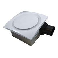
This document describes the Aero Pure AP90-S, AP90H-S, AP120-S, and AP120H-S ventilation fans, providing detailed instructions for installation, operation, maintenance, and safety.
The primary function of these devices is to provide ventilation, designed for general ventilating use in ceilings up to a 12/12 pitch (45-degree angle). They are suitable for use over a tub or shower when connected to a GFCI (Ground Fault Circuit Interrupter) protected branch circuit, but only for ceiling installations in such wet areas. It is explicitly stated that these fans are not to be used in kitchens and should not be installed in a cooking area or directly above or inside it. For wall applications, the duct connector must point upwards. The fan should be installed at least 2.5 meters (8 feet) above the floor.
Several usage features are highlighted. The fan operates with an on/off switch. For models AP90H-S and AP120H-S, the humidity control and fan can be operated separately, requiring a 1- or 2-function wall control. A dimmer switch should not be used to operate the humidity control. These models incorporate a sophisticated humidity sensor that responds to rapid to moderate (user-adjustable) increases in humidity or humidity levels above a user-adjustable set-point (50%-100% relative humidity). The humidity sensor may occasionally activate the fan when environmental conditions change. If the fan continuously responds to changing environmental conditions, the "H" (humidity) adjustment may need to be modified. The factory setting for humidity is approximately 75% RH, suitable for most shower applications. However, if the fan is in a tub area or used for dampness control, the "H" may need to be increased towards maximum ("+") or decreased towards minimum ("-") if the control is responding too often. The adjustment involves disconnecting power, locating the "H" slot through the grille, carefully rotating the adjustment, and then checking operation.
Additionally, the humidity-sensing fans include a "T" (timer) function, adjustable from 5 to 60 minutes, with a factory setting of about 20 minutes. This timer controls how long the fan remains on after the sensor stops detecting a rise in humidity and the humidity level drops below the user-adjustable set-point. Adjusting the timer also requires disconnecting power, locating the "T" slot through the grille, rotating it to the desired setting, and then checking the operation by turning on a humidity source and timing the unit.
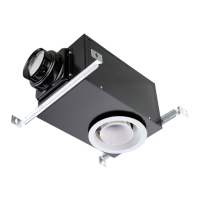
Installation involves several steps. Before installation, users need to identify the appropriate screws and hanger bar lengths. The fan can be mounted using mounting holes and hanger bars, or with hanger bars only, or specifically to I-joists. The instructions provide different options for hanger bar placement depending on the distance between framing members. Ductwork connection is crucial for proper performance. Round ductwork (not included) should be connected to the damper/duct connector and routed to a roof or wall cap (not included). Duct tape is used to secure connections for airtightness. Insulated flexible duct is recommended for quiet operation, or a short section of insulated flexible duct if rigid duct is used. The document emphasizes keeping duct runs short and straight to maximize airflow, minimize noise, and reduce energy use. Electrical wiring involves running 120V AC house wiring to the fan's location using UL-approved connectors. Wiring diagrams are provided for both standard and humidity-sensing models. Finally, the grille is installed after ceiling construction is complete by pinching its springs and positioning it into the housing slots.
Maintenance features are simple and designed for long-term, quiet, and efficient operation. For cleaning, the grille can be lowered or removed, and the interior of the unit can be vacuumed using a dusting brush attachment. The motor is permanently lubricated and does not require oiling, simplifying maintenance.
Safety warnings are extensive and critical. Users are instructed to use the unit only as intended by the manufacturer. Before servicing or cleaning, power must be switched off at the service panel and locked to prevent accidental re-energization. Installation and electrical wiring must be performed by licensed personnel in accordance with all applicable codes and standards, including fire-rated construction codes. Adequate air supply is necessary for proper combustion and exhausting of gases from fuel-burning equipment to prevent backdraft, following guidelines from NFPA, ASHRAE, and local code authorities. Users must avoid damaging electrical wiring or other hidden utilities when cutting or drilling into walls or ceilings. Ducted fans must always vent to the outdoors. The unit must be grounded. Switches should not be placed where they can be reached from a tub or shower. The fan should not be used with any solid-state speed control device. Finally, the fan must not be installed in a ceiling thermally insulated to a value greater than R40. The manual also warns against using the fan to exhaust hazardous or explosive materials and vapors.
| Model | AP90-S |
|---|---|
| Voltage | 220-240V |
| Dimensions | 10.25 x 10.25 x 7.75 in. |
| Sound Level | <0.3 Sones |
| Frequency | 60 Hz |
| Noise Level | <0.3 Sones |