DATA CONNECTOR AND TIMING
77
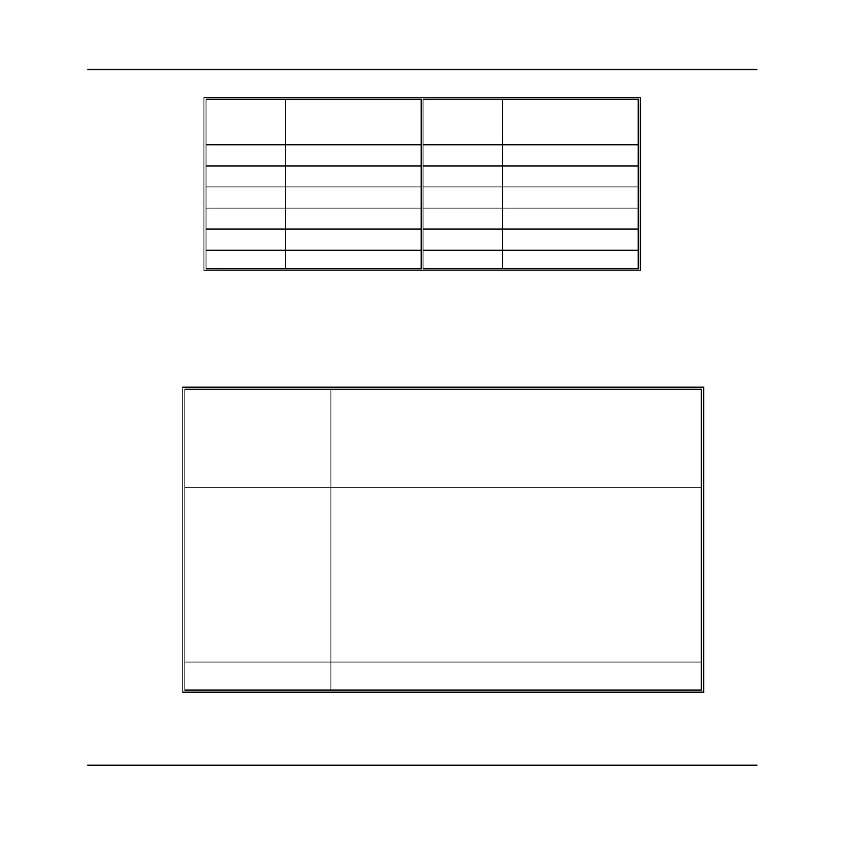
Contact Function Contact Function
28 GND 62 GND
29
MARKER1−
63 MARKER1+
30
MARKER2−
64 MARKER2+
31
MARKER3−
65 MARKER3+
32
MARKER4−
66 MARKER4+
33
AUX3−
67 AUX3+
34
AUX4−
68 AUX4+
Data format (3030C/3035C/3036 only)
The data output to the DATA interface is real-time. In resample mode, data is output using a
180 MHz, 125 MHz or 62.5 MHz clock (depending on LVDS clock rate). The data is bursted
to achieve the correct average sample rate.
D0-D15 (Sample
DATA) in Output Mode
Sample Data Output Format:
16-bit IQ: 2 x D[15:0], I followed by Q, D[0]=LSB.
32-bit IQ: 4 x D[15:0] in order I MSW, I LSW, Q MSW, Q LSW,
D[0]=LSB.
IQSELECT_OUT Specifies content of D0-D15 in output mode when sample data
format is IQ. IQSELECT=1 for rising CLK_OUT indicated I
data on D0-D15. First IQSELECT transition to ‘0’ from ‘1’ on
the rising edge of CLK_OUT indicates start of the Q data. In
16-bit mode, Q data is valid for one clock whereas in 32-bit
mode, Q data is valid for two clocks after IQSELECT changes
to 0. Note that IQSELECT stays 0 even if Q data is
transferred. Thereafter, Q is indeterminate until
IQSELECT_OUT goes positive to define a new IQ pair.
IQSELECT_OUT stays =0 at all times in IF mode.
CLK_OUT Output clock signal.

 Loading...
