Subject to Export Control, see Cover Page for details. 2-99
2-5-4. MEASURING SWR (cont)
6. Connect the System Under Test to the SWR Connector at the point of calibration.
7. The Graphical Display is updated approximately every 20 seconds. Allow at least two
updates of the Graphical Display to insure data is valid.
NOTE: The 3500 / 3500A checks the electrical length of the load under test. If the
frequency span selected is too wide, the 3500 / 3500A automatically adjusts the
frequency span to insure an accurate measurement, and displays ‘Span Clipped’
above the graphical display to alert the user the frequency span was changed.
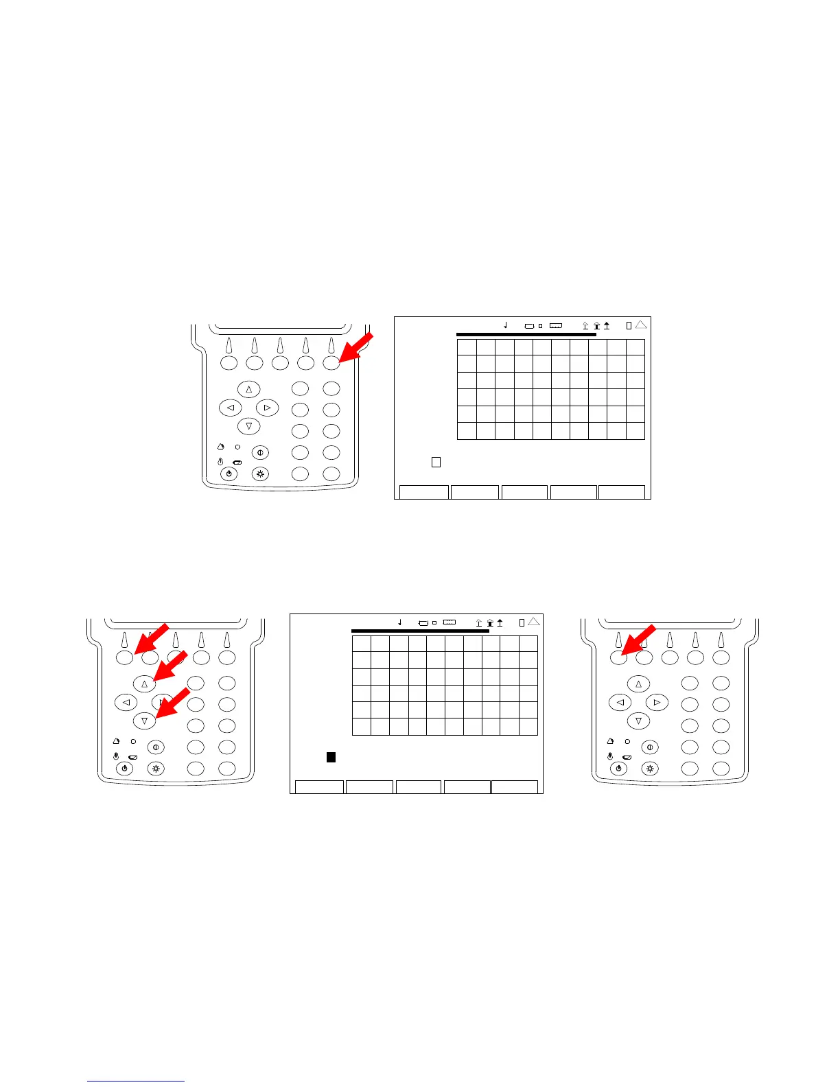
8. Press the F5 ”Marker” Key to display the ANT-Cable Test Screen in Marker Mode.
2
4
6
8
0
1
9
7
5
3
ANT-CABLE TEST
7.00
2009-01-06
11:35:30
SWR
1.00
35.0 MHz 45.0
Ma r ke r : 1 O f f Del ta: 1 Po s: 0 .00 De lt a 0 .00
Mo ve Lef t R ight V SW R 0. 00 Del ta 0 .00
Edit
Return
Ho l d
Cal
Scale
4 1 20 29
9. With the data displayed on the Graphical Display, the Markers are used to determine the
SWR at any point across the span. With the cursor on the Marker Number Field, use the
UP Key or DOWN Key to select a Marker (1, 2 or 3). Press the F1 “Done” Key to save
the setting.
2
4
6
8
0
1
9
7
5
3
ANT-CA BLE TEST
7.00
200 9-01 -06
11 :35 : 30
SWR
1.00
35.0 MHz
4 5.0
Ma r ke r : 1 Off Delta: 1 Pos: 0.00 Delta 0.00
Move Left Right VSWR 0.00 Delta 0.00
Edit Return Ho l d Cal Scale
41 20 29
2
4
6
8
0
1
9
7
5
3
 Loading...


