Subject to Export Control, see Cover Page for details. 2-107
2-5-5. MEASURING DTF (Distance to Fault) (cont)
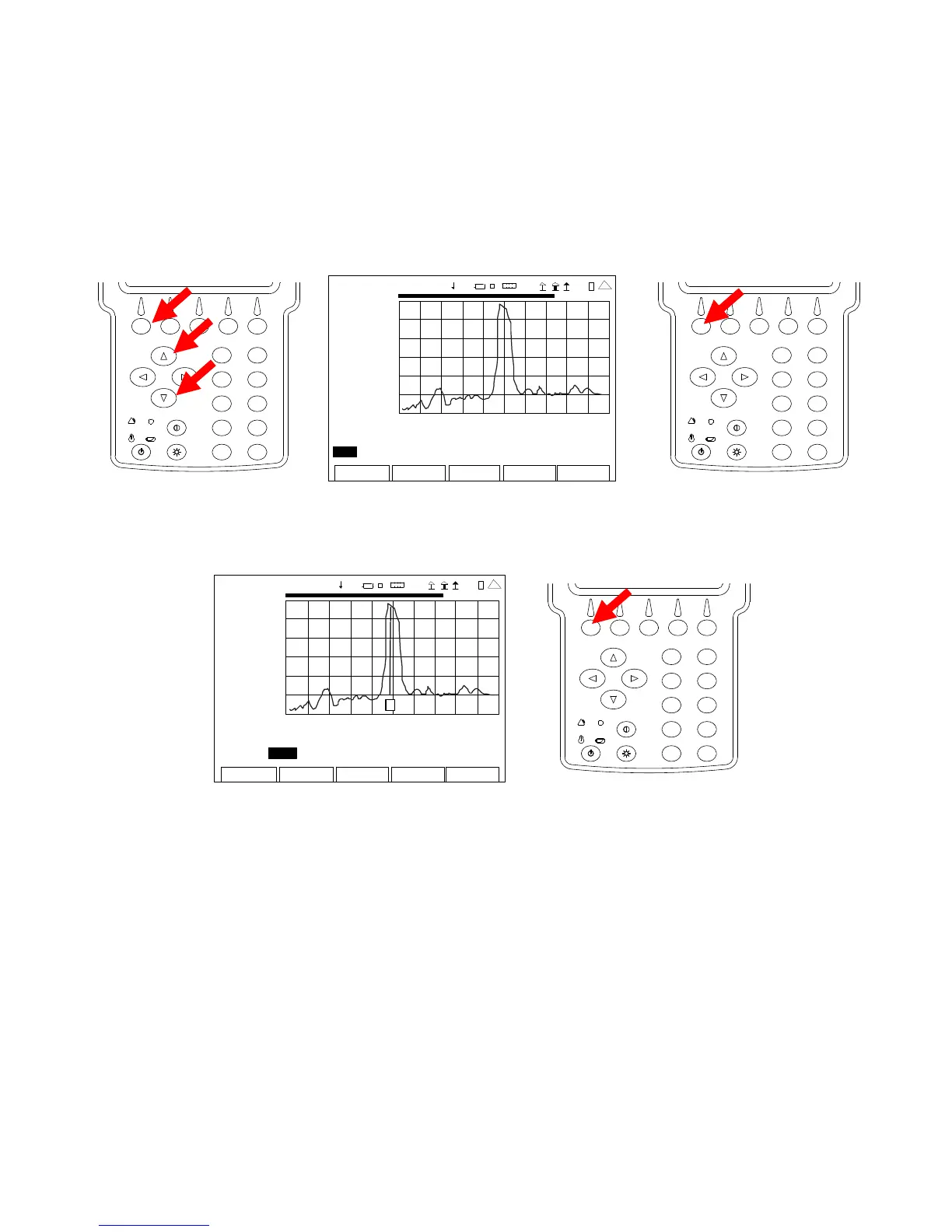
16. With the cursor on the Peak/Move Field, press the F1 “Edit” Key and use the UP Key or
DOWN Key to select Peak or Move. Press the F1 “Done” Key to save the setting.
NOTE: Selecting “Peak” moves the Marker to the Next Peak on the Graphical Display.
Selecting “Move” moves the Marker to the next Data Point on the Graphical
Display.
2
4
6
8
0
1
9
7
5
3
AN
-CABL E TEST
0.00
200 9-01 -06
11 :35 : 30
dB
-50 .0
0.0 ft 408.8
Marker: 1 Off Delta: 1 Pos: 0.00 Delta 0.00
Mo v e Left Right dB 0.00 Delta 0.00
Edit Return
Ho l
Cal
Cable
41 20 29
2
4
6
8
0
1
9
7
5
3
17. With the cursor on the Right Field, press the F1 “Enter” Key to move the Marker to the right
on the Graphical Display.
ANT-CABLE TEST
0.00
2009-01-06
11:35:30
dB
-50 .0
0.0 ft 408.8
Ma r ke r : 1 O f f Del ta: 1 Po s: 0 .00 De lt a 0 .00
Move Left Right dB 0.00 Delta 0.00
Edit Return Ho l d Cal
Cable
1
4 1 20 29
2
4
6
8
0
1
9
7
5
3
NOTE: When first enabled, a Marker is at the far left of the Graphical Display. Up to
three Markers may be placed on the Graphical Display at a time. The Marker
shown in the Marker Number Field is active. The active Marker can be moved
using the Peak/Move and Left Right Fields with the readings, corresponding to the
Marker position, displayed in fields under the Graphical Display.
 Loading...


