Subject to Export Control, see Cover Page for details. 2-109
2-5-6. MEASURING REVERSE POWER (cont)
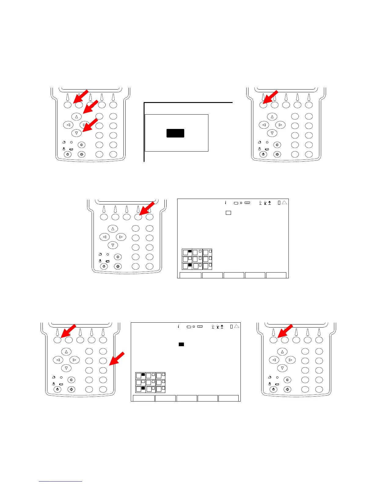
3. With the cursor on the Port (RF In) Field, press the F1 “Edit” Key and use the UP Key or
DOWN Key to select the T/R Connector. Press the F1 “Done” Key to save the setting.
2
4
6
8
0
1
9
7
5
3
TRANSMITTER TEST
Recei ver More
MHz: 4 0.0 000 00
Port: T/R
Mo d: FM 10 k
AFBW : Non e
2
4
6
8
0
1
9
7
5
3
4. Press the F4 “Setup” Key to display the Transmitter Test Setup Screen.
2
4
6
8
0
1
9
7
5
3
TX TEST SETUP
Fgen 0 DTMF Decode 0
Modulation Meter: 0 DCS Decod e 0
R SSI Mete r : 0 Audio Leve l 0
RF Error Meter: 0
D istor ti on Mete r : 0
SINAD Meter 0
RF Power Meter 0
AF Cou nte r 0
Edit Return
1
7
2
5
8
3
41 20 29
5. With the cursor on the RSSI Meter Field, press the F1 “Edit” Key and the Number Key for an
open Meter position (refer to Meter Chart) to display the RSSI Meter in that position on the
Transmitter Test Screen. Press the F1 “Done” Key to save the setting.
2
4
6
8
0
1
9
7
5
3
TX TEST SETUP
F gen 0 DTMF Decode 0
Mo dulati on Me ter : 0 DCS Decod e 0
RSSI Meter: 3 Audio Level 0
RF Error Meter: 0
D istor ti on Mete r : 0
SINAD Meter 0
RF Power Meter 0
A F Cou nte r 0
Do n e Return
1
7
2
5
8
41 20 29
2
4
6
8
0
1
9
7
5
3
 Loading...


