Soloist Hardware Manual List of Figures
www.aerotech.com v
LIST OF FIGURES
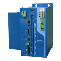
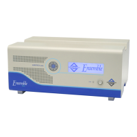
Figure 1-1 Soloist in TwoVersions.......................................................................1-1
Figure 1-2 Soloist Hardware.................................................................................1-3
Figure 1-3 Soloist Block Diagram........................................................................1-4
Figure 1-4 Soloist Physical Dimensions ...............................................................1-8
Figure 2-1 -AUXPWR Option..............................................................................2-5
Figure 2-2 40 Volt DC Bus from 115 and 230 VAC Source................................2-6
Figure 2-3 80 Volt DC Bus from 115 and 230 VAC Source................................2-7
Figure 2-4 160 Volt DC Bus from 115 and 230 VAC Source..............................2-8
Figure 2-5 Back-Propagation Line Filter Connection...........................................2-9
Figure 2-6 ESTOP Sense Input (TB101)............................................................2-10
Figure 2-7 Typical Emergency Stop Circuit .......................................................2-11
Figure 2-8 DC Brush Motor (Torque Mode) Connections .................................2-12
Figure 2-9 Brushless Motor Connections ...........................................................2-13
Figure 2-10 Hall Effect Feedback Connections....................................................2-15
Figure 2-11 Hall Effect Feedback Inputs in the Soloist HMI Program.................2-15
Figure 2-12 Motor Phasing...................................................................................2-17
Figure 2-13 Stepper Motor Connections...............................................................2-18
Figure 2-14 Encoder Feedback Connections ........................................................2-19
Figure 2-15 Encoder Phasing Reference Diagram................................................2-20
Figure 2-16 Encoder Feedback in the Soloist HMI ..............................................2-20
Figure 2-17 Limit Inputs in the Soloist HMI Program..........................................2-21
Figure 2-18 Limit Inputs in the Soloist HMI Program..........................................2-21
Figure 3-1. PSO Interface (J104)...........................................................................3-3
Figure 3-2. Primary / Secondary Encoder Channels (J103, J104) .........................3-4
Figure 3-3. User Outputs (J104) ............................................................................3-6
Figure 3-4. Outputs Connected as Current Sinking ...............................................3-7
Figure 3-5. Outputs Connected as Current Sourcing .............................................3-7
Figure 3-6. Connecting Current Sinking Inputs.....................................................3-9
Figure 3-7. Connecting Current Sourcing Inputs...................................................3-9
Figure 3-8. Low Speed and High Speed User Inputs (J104)................................3-10
Figure 3-9. Analog Output 0 (J104).....................................................................3-11
Figure 3-10. Analog Input 0 (J104) .......................................................................3-12
Figure 3-11. PSO Block Diagram..........................................................................3-14
Figure 3-12. Data Capture/Data Update Modes.....................................................3-14
Figure 3-13. Limit, Thermistor and Hall-Effect Inputs (J103)..............................3-16
Figure 3-14. Optional -MXU Analog Encoder Interface (J103)............................3-17
Figure 3-15. Brake Connector (TB103).................................................................3-18
Figure 3-16. RS-232 Connector (TB103)..............................................................3-19
Figure 4-1. –IO Option Board (690D1611 Rev. 0)................................................4-2
Figure 4-2. Optional Analog Input Connector (TB201) ........................................4-2
Figure 4-3. Analog Output Connector (TB201).....................................................4-3
Figure 4-4. Connecting Outputs in Current Sinking Mode ....................................4-5
Figure 4-5. Connecting Outputs in Current Sourcing Mode..................................4-5
Figure 4-6. Inputs Connected in Current Sourcing Mode......................................4-7
Figure 4-7. Inputs Connected in Current Sinking Mode........................................4-8


 To Next Page