2726
EPIC 2DEPIC 2DInstallation General use
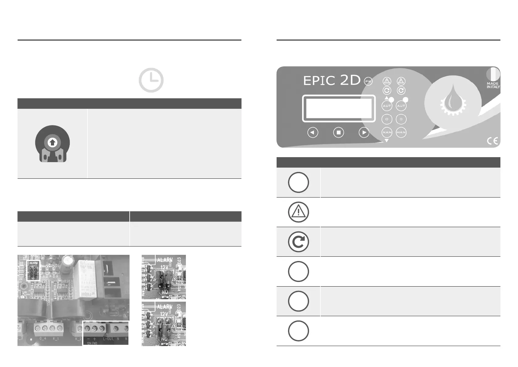
3.5 TRIMMER SETTINGS
TRIMMER SETTING
+ –
TRIMMER 1: PROBE SENSITIVITY CHANGE
Probe sensivity (CLC) and water in oil chamber sensor trimmer
regulation.
It is possible to change the sensitivity of the CLC probes and the
water sensor in the oil chamber, interrupting the power supply
to the control panel and acting on trimmer 1 (clockwise to
increase and counterclockwise to decrease sensitivity).
3.6 ALARM CONTACT OUTPUTS
SINGLE PHASE VERSION TREE PHASE VERSION
Alarm outputs:
• L-OUT / N = 230 V c.a.
• + -12 / NO = 12V c.c. or contact NO
Alarm outputs:
• L-OUT / N = 400 V c.a.
• + -12 / NO = 12V c.c. or contact NO
12 V c.c. output
free contact NO
To change manually the threshold protections,
interrupt the power supply to the control
panel and work on the trimmers, please
following the below instructions:
PROTECTION DELAY
The pump protection switching
delay has been set at 5 sec.
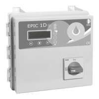
CONTROL PANEL
PW
PW
blue light indicating power network presence and powered panel.
ALARM
red light to indicate a general alarm and pump stop. (min e max Amp, min
e max V, min e max level, motor klixon, water in oil chamber, phase failure).
START
green light to indicate pump start; fixed on to indicate pump running, flashing
to indicate auto-setting mode.
AUT
AUT
the button activates the auto-setting mode and automatic pump
(if the green light is on, the automatic mode is active).
0
0
pump stop button and reset alarms, sound alarm turn-off.
MAN
MAN
activation of manual pump; holding it down, the engine is operated in by-pass
mode, bypassing all the protections.
4.1 KEYPAD AND LIGHTS INDICATIONS