The Noyes OPM 5 OLS 2 D is a series of optical power meters and optical light sources, designed for testing and inspecting fiber optic networks. This user guide covers the OPM4 and OPM5 optical power meters, and the OLS1, OLS2, OLS4, OLS7-3, and OLS7-FTTH optical light sources, along with related test kits.
Function Description
The OPM series optical power meters are used to measure optical power in dBm, µW, or insertion loss in dB. They can display measurements for single wavelength, dual wavelength, and tri wavelength modes. The OPMs are capable of storing test results and managing files. The OLS series optical light sources provide stable light output at various wavelengths (e.g., 850 nm, 1300 nm, 1310 nm, 1550 nm, 1625 nm, 1490 nm, 1650 nm) for testing fiber optic cables. Some OLS models offer continuous wave (CW) mode and various tone frequencies (1 kHz, 2 kHz, 330 Hz, 270 Hz) for identification. The devices are designed for both multimode and single-mode link testing.
Important Technical Specifications
- OPM Series (OPM4, OPM5) Optical Power Meters:
- Measurement Units: dBm, µW, dB, Hz.
- Wavelengths: Supports various wavelengths for testing, with automatic switching based on detected ID.
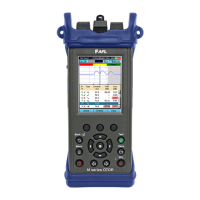
- Display: Shows measured power, insertion loss, tone signal, wavelength ID, references, and battery charge status.
- Memory: Stores test results. OPM5 has advanced file management capabilities.
- Connectivity: Mini-USB port for AC power adapter or PC connection (OPM5).
- Power: Battery operated, with battery status indicator.
- OLS Series Optical Light Sources:
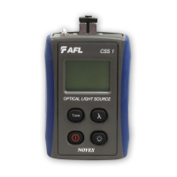
- OLS1 Dual LED Light Source:
- Wavelengths: 850 nm, 1300 nm.
- Modes: Dual WAVE ID, single WAVE ID, CW.
- Output: Continuous light, blinking light.
- OLS2 Dual Laser Source:
- Wavelengths: 1310 nm, 1550 nm.
- Modes: WAVE ID, CW, 1 kHz, 2 kHz, 330 Hz, 270 Hz.
- Output: Continuous light, blinking light.
- Output Adjust: Allows adjustment of optical power output.
- OLS4 Integrated LED and Laser Light Source:
- Wavelengths: 850 nm, 1300 nm, 1310 nm, 1550 nm.
- Modes: Dual WAVE ID, single WAVE ID, CW, 1 kHz, 2 kHz, 330 Hz, 270 Hz.
- Output: Continuous light, blinking light.
- OLS7-3 Triple Wavelength Laser Source:
- Wavelengths: 1310 nm, 1550 nm, 1625 nm.
- Modes: WAVE ID, CW, 1 kHz, 2 kHz, 330 Hz, 270 Hz.
- Output: Continuous light, blinking light.
- Output Adjust: Allows adjustment of optical power output.
- OLS7-FTTH Triple Wavelength Laser Source:
- Wavelengths: 1310 nm, 1490 nm, 1650 nm.
- Modes: WAVE ID, CW, 1 kHz, 2 kHz, 330 Hz, 270 Hz.
- Output: Continuous light, blinking light.
- Output Adjust: Allows adjustment of optical power output.
- Connectors: Universal Connector Interface (UCI) accepts swappable SC connector (ST, FC, and LC connector styles are available).
Usage Features
- User-Friendly Interface: Both OPM and OLS devices feature intuitive button layouts for easy operation.
- Display Readings: The OPMs provide clear digital displays of measurements, battery status, and selected settings.
- Power Key: Turns the device on/off and enables/disables the Auto Off feature.
- Wavelength/Backlight Key: Toggles backlight on/off and cycles through calibrated wavelengths.
- dB/dBm/µW Key: Changes the measurement unit.
- Ref/Set Key: Sets and displays reference levels for insertion loss measurements.
- Store Key (OPM5): Saves current measurements to memory.
- Recall Key (OPM5): Recalls stored measurements for viewing and deleting.
- Clear Key (OPM5): Erases stored files or fiber data.
- File Manager (OPM5): Allows selection, creation, and deletion of files and fibers for organized data storage.
- Output Adjust (OLS2, OLS7-3, OLS7-FTTH): Allows users to increase or decrease the optical output power.
- Tone Key (OLS4): Enables or disables 2kHz Tone mode on the SM port.
- Testing Procedures: The manual outlines detailed steps for testing multimode and single-mode links, including setting references (one jumper method), verifying test jumpers, and measuring insertion loss.
- Adapter Caps: OPMs accept NOYES thread-on adapter caps, and OPM5 optical input must be equipped with an adapter cap.
Maintenance Features
- Cleaning Optical Ports: Regular cleaning of optical ports is crucial for accurate measurements and operation.
- Unscrew adapter cap: Remove the adapter cap from the adapter mount.
- Lint-free optical cleaning wipes: Use AFL FiberWipes and optical quality cleaning fluid (IPA - Reagent Grade Isopropyl Alcohol 99% or better) or a can of filtered compressed air.
- Dampen wipe: Dampen a portion of the wipe with cleaning fluid.
- Gently wipe: Gently wipe the exposed OPM port starting with the wet section of the wipe and pulling it to the dry section.
- End-face dry: Starting with the wet cleaning and finishing in the dry improves cleaning action, reduces static buildup, and finishes with the end-face dry.
- Compressed air: Use a can of filtered compressed air (held vertically) to blow out any contaminants from the adapter cap.
- Replace adapter cap: Once cleaning is complete.
- Cleaning OLS Optical Ports without removing adapters:
- Protective dust cover: Remove the protective dust cover from the tip of the One-Click Cleaner.
- Insert tip: Insert the tip of the One-Click Cleaner into the optical port adapter and gently press the body of the One-Click Cleaner until an audible "click" is heard.
- Remove: Remove the One-Click Cleaner.
- Cleaning OLS Optical Ports with Adapters Removed:
- Rotate adapter base: Rotate the adapter base counterclockwise approximately four times.
- Pull adapter: Pull the adapter directly out away from the adapter mount.
- Perform cleaning: Follow the same cleaning steps as for OPM optical ports.
- AFL FCC2 fluid and CCT stick method:
- Leaning FCC2: Leaning the FCC2 can back (30°), press the button on the FCC2 to fill the well.
- Dip CCTP tip: Dip the CCTP tip into the well of the FCC2 to dampen the tip with optical cleaning fluid.
- Place damp tip: Place the damp tip over the ferrule to be cleaned.
- Rotate tip: Rotate the tip clockwise 10 revolutions while applying varying pressure to create a gentle pumping action where the tip contacts the ferrule.
- Discard CCTP stick: Discard the CCTP stick after using both tips.
- Using lint-free optical cleaning pads and isopropyl alcohol:
- Be sure to use 99% IPA: Ensure the IPA is not contaminated.
- Dampen wipe: Dampen the wipe with the alcohol and gently wipe the exposed ferrule. Then dry the ferrule using a new optical wipe.
- Repair and Calibration: Repair of NOYES test equipment is not recommended. Calibration is recommended every 12 months. NOYES Calibration Department is in compliance with ANSI/NCSL Z540-1, ISO 10012-1, MIL STD 45662A, ISO Guide 25 and traceability to the National Institute of Standards and Technology.
- Battery Replacement:
- Remove the protective rubber boot from the instrument.
- Remove the battery compartment cover located on the back of the instrument.
- Replace the two discharged AA batteries.
- Replace the battery compartment cover and rubber boot.
- Mandrels for Multimode Transmit Jumpers: When testing multimode links, using an overfilled LED source, always wrap the transmit jumper five (5) times around the proper diameter mandrel. This is specified by TIA/EIA-568-B and will improve insertion loss measurement repeatability and accuracy. Do not use mandrels on multimode receive jumpers or single-mode jumpers.