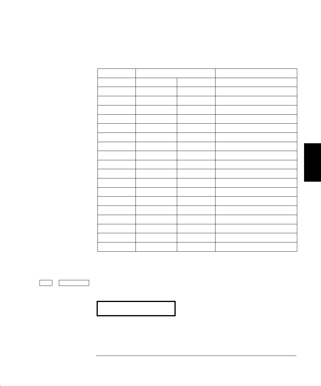
3 For each setup in the table below, use the CALIBRATE command to
change the displayed amplitude to match the measured amplitude.
Nominal Output
SETUP FREQUENCY AMPLITUDE Adjustment for:
65 100 kHz 3.0 V rms 100 kHz amplitude flatness
66 500 kHz 3.0 V rms 500 kHz amplitude flatness
67 1 MHz 3.0 V rms 1 MHz amplitude flatness
68 3 MHz 3.0 V rms 3 MHz amplitude flatness
69 5 MHz 3.0 V rms 5 MHz amplitude flatness
70 7 MHz 3.0 V rms 7 MHz amplitude flatness
71 9 MHz 3.0 V rms 9 MHz amplitude flatness
72 10 MHz 3.0 V rms 10 MHz amplitude flatness
73 10.5 MHz 3.0 V rms 10.5 MHz amplitude flatness
74 11 MHz 3.0 V rms 11 MHz amplitude flatness
75 11.5 MHz 3.0 V rms 11.5 MHz amplitude flatness
76 12 MHz 3.0 V rms 12 MHz amplitude flatness
77 12.5 MHz 3.0 V rms 12.5 MHz amplitude flatness
78 13 MHz 3.0 V rms 13 MHz amplitude flatness
79 13.5 MHz 3.0 V rms 13.5 MHz amplitude flatness
80 14 MHz 3.0 V rms 14 MHz amplitude flatness
81 14.5 MHz 3.0 V rms 14.5 MHz amplitude flatness
82 15 MHz 3.0 V rms 15 MHz amplitude flatness
4 Perform the Amplitude Flatness Verification procedures on page 60.
Shift Menu On/Off Completion of adjustment procedures. Return the function generator
to the normal operating mode.
EXITING
4
Chapter 4 Calibration Procedures
AC Amplitude Flatness Adjustment
79

 Loading...


