4349B
T
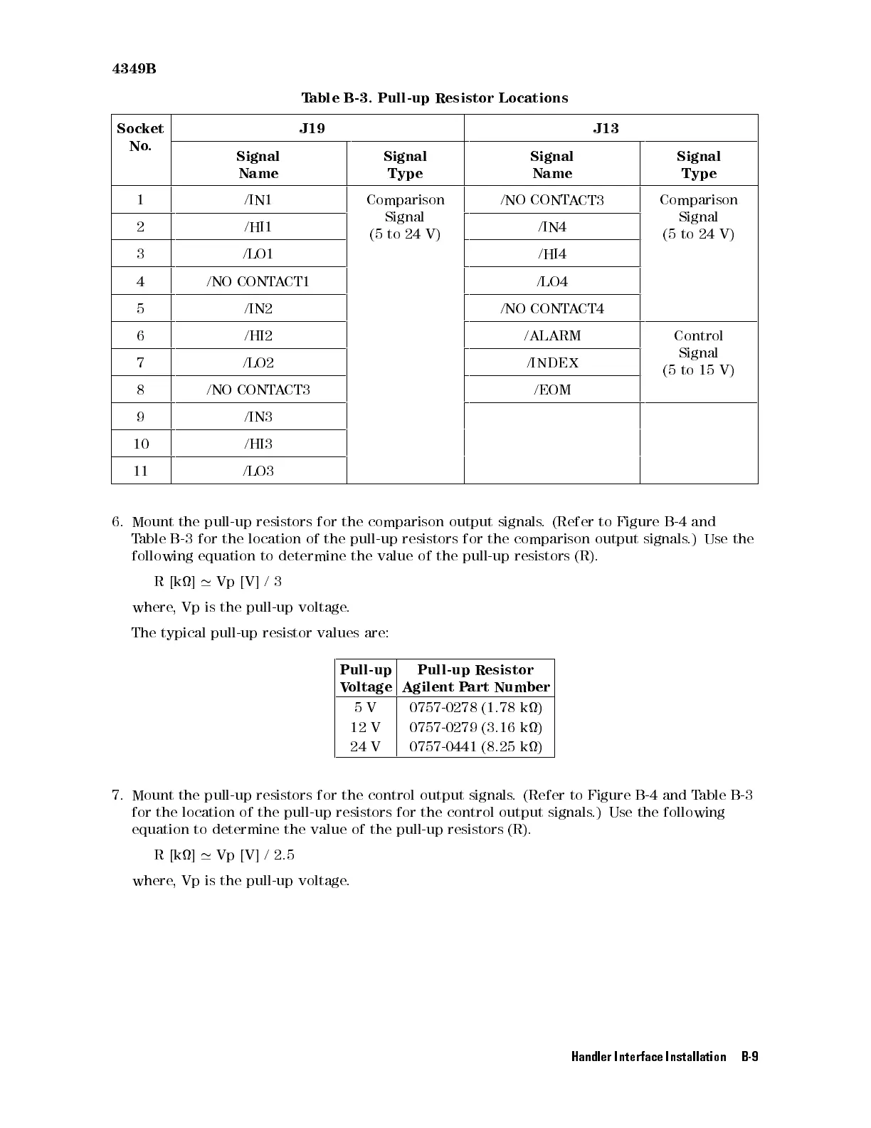
able B-3.
Pull-up Resistor
Locations
Socket
No
.
J19 J13
Signal
Name
Signal
Type
Signal
Name
Signal
Type
1 /IN1 Comparison
Signal
(5
to
24
V)
/NO
CONT
A
CT3
Comparison
Signal
(5
to
24
V)
2 /HI1 /IN4
3 /LO1 /HI4
4 /NO
CONTA
CT1
/LO4
5 /IN2 /NO
CONT
A
CT4
6 /HI2 /ALARM Control
Signal
(5
to
15
V)
7 /LO2 /INDEX
8 /NO
CONT
A
CT3
/EOM
9 /IN3
10 /HI3
11 /LO3
6.
Mount
the
pull-up
resistors
for
the
comparison
output
signals
.
(Refer
to
Figure
B-4
and
T
able
B-3
for
the
location
of
the
pull-up
resistors
for
the
comparison
output
signals
.) Use
the
following
equation
to
determine
the
value
of
the
pull-up
resistors
(R).
R
[k]
'
Vp
[V]
/
3
where
,
Vp
is
the
pull-up
voltage
.
The
typical
pull-up
resistor
values
are:
Pull-up
V
oltage
Pull-up
Resistor
Agilent
P
art
Number
5
V
0757-0278
(1.78
k)
12 V 0757-0279 (3.16
k)
24
V
0757-0441
(8.25
k)
7. Mount the pull-up
resistors for the control output signals
. (Refer to Figure B-4 and T
able B-3
for the location of the pull-up resistors for the control output signals
.) Use
the following
equation to determine the value of the pull-up resistors (R).
R [k]
'
Vp [V] / 2.5
where, Vp is the pull-up voltage
.
Handler Interface Installation B-9
 Loading...