22
Accuracy Specifications ± (% of reading + % of range)
1
Function Range
3
Frequency, 24 Hour
2
90 Day 1 Year
Temperature Coefficient
etc. 23°C ±1°C 23°C ±5°C 23°C ±5°C 0°C – 18°C
28°C – 55°C
DC voltage 100.0000 mV 0.0030 + 0.0030 0.0040 + 0.0035 0.0050 + 0.0035 0.0005 + 0.0005
1.000000 V 0.0020 + 0.0006 0.0030 + 0.0007 0.0040 + 0.0007 0.0005 + 0.0001
10.00000 V 0.0015 + 0.0004 0.0020 + 0.0005 0.0035 + 0.0005 0.0005 + 0.0001
100.0000 V 0.0020 + 0.0006 0.0035 + 0.0006 0.0045 + 0.0006 0.0005 + 0.0001
1000.000 V 0.0020 + 0.0006 0.0035 + 0.0010 0.0045 + 0.0010 0.0005 + 0.0001
True rms 100.0000 mV 3 Hz – 5 Hz 1.00 + 0.03 1.00 + 0.04 1.00 + 0.04 0.100 + 0.004
AC voltage
4
5 Hz – 10 Hz 0.35 + 0.03 0.35 + 0.04 0.35 + 0.04 0.035 + 0.004
10 Hz – 20 kHz 0.04 + 0.03 0.05 + 0.04 0.06 + 0.04 0.005 + 0.004
20 kHz – 50 kHz 0.10 + 0.05 0.11 + 0.05 0.12 + 0.05 0.011 + 0.005
50 kHz – 100 kHz 0.55 + 0.08 0.60 + 0.08 0.60 + 0.08 0.060 + 0.008
100 kHz – 300 kHz
6
4.00 + 0.50 4.00 + 0.50 4.00 + 0.50 0.20 + 0.02
1.000000 V 3 Hz – 5 Hz 1.00 + 0.02 1.00 + 0.03 1.00 + 0.03 0.100 + 0.003
to 750.000 V 5 Hz –10 Hz 0.35 + 0.02 0.35 + 0.03 0.35 + 0.03 0.035 + 0.003
10 Hz – 20 kHz 0.04 + 0.02 0.05 + 0.03 0.06 + 0.03 0.005 + 0.003
20 kHz – 50 kHz 0.10 + 0.04 0.11 + 0.05 0.12 + 0.04 0.011 + 0.005
50 kHz – 100 kHz
5
0.55 + 0.08 0.60 + 0.08 0.60 + 0.08 0.060 + 0.008
100 kHz – 300 kHz
6
4.00 + 0.50 4.00 + 0.50 4.00 + 0.50 0.20 + 0.02
Resistance
7
100.0000 Ω 1 mA
Current Source
0.0030 + 0.0030 0.008 + 0.004 0.010 + 0.004 0.0006 + 0.0005
1.000000 kΩ 1 mA 0.0020 + 0.0005 0.008 + 0.001 0.010 + 0.001 0.0006 + 0.0001
10.00000 kΩ 100 µA 0.0020 + 0.0005 0.008 + 0.001 0.010 + 0.001 0.0006 + 0.0001
100.0000 kΩ 10 µA 0.0020 + 0.0005 0.008 + 0.001 0.010 + 0.001 0.0006 + 0.0001
1.000000 MΩ 5.0 µA 0.002 + 0.001 0.008 + 0.001 0.010 + 0.001 0.0010 + 0.0002
10.00000 MΩ 500 nA 0.015 + 0.001 0.020 + 0.001 0.040 + 0.001 0.0030 + 0.0004
100.0000 MΩ 500 nA || 10 MΩ 0.300 + 0.010 0.800 + 0.010 0.800 + 0.010 0.1500 + 0.0002
DC current 10.00000 mA < 0.1 V
Burden Voltage
0.005 + 0.010 0.030 + 0.020 0.050 + 0.020 0.0020 + 0.0020
100.0000 mA < 0.6 V 0.010 + 0.004 0.030 + 0.005 0.050 + 0.005 0.0020 + 0.0005
1.000000 A < 1.0 V 0.050 + 0.006 0.080 + 0.010 0.100 + 0.010 0.0050 + 0.0010
3.00000 A < 2.0 V 0.100 + 0.020 0.120 + 0.020 0.120 + 0.020 0.005 + 0.0020
True rms 1.000000 A 3 Hz – 5 Hz 1.00 + 0.04 1.00 + 0.04 1.00 + 0.04 0.100 + 0.006
AC current
4
5 Hz – 10 Hz 0.30 + 0.04 0.30 + 0.04 0.30 + 0.04 0.035 + 0.006
10 Hz – 5 kHz 0.10 + 0.04 0.10 + 0.04 0.10 + 0.04 0.015 + 0.006
3.00000 A 3 Hz – 5 Hz 1.10 + 0.06 1.10 + 0.06 1.10 + 0.06 0.100 + 0.006
5 Hz – 10 Hz 0.35 + 0.06 0.35 + 0.06 0.35 + 0.06 0.035 + 0.006
10 Hz – 5 kHz 0.15 + 0.06 0.15 + 0.06 0.15 + 0.06 0.015 + 0.006
Frequency 100 mV to 3 Hz – 5 Hz 0.10 0.10 0.10 0.005
or period
8
750 V 5 Hz – 10 Hz 0.05 0.05 0.05 0.005
10 Hz – 40 Hz 0.03 0.03 0.03 0.001
40 Hz – 300 kHz 0.006 0.01 0.01 0.001
Continuity 1000.0 Ω 1 mA test current 0.002 + 0.030 0.008 + 0.030 0.010 + 0.030 0.001 + 0.002
Diode test
9
1.0000 V 1 mA test current 0.002 + 0.010 0.008 + 0.020 0.010 + 0.020 0.001 + 0.002
1. Specifications are for 1 hr warm-up and 6½ digits, slow ac filter.
2. Relative to calibration standards.
3. 20% over range on all ranges except 1000 Vdc and 750 Vac ranges.
4. For sinewave input > 5% of range. For inputs from 1% to 5% of range
and < 50 kHz, add 0.1% of range additional error.
5. 750 V range limited to 100 kHz or 8 x 10
7
Volt-Hz.
6. Typically 30% of reading error at 1 MHz.
7. Specifications are for 4-wire ohms function or 2-wire ohms using Math
Null. Without Math Null, add 0.2 Ω additional error in 2-wire ohms
function.
8. Input >100 mV. For 10 mV to 100 mV inputs multiply % of reading
error x10.
9. Accuracy specifications are for the voltage measured at the input termi-
nals only. 1 mA test current is typical. Variation in the current source will
create some variation in the voltage drop across a diode junction.
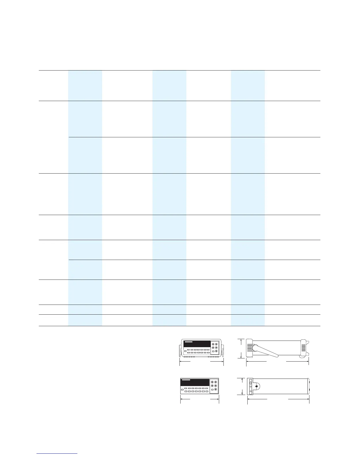
254.4 mm
103.6 mm
374.0 mm
212.6 mm
348.3 mm
88.5 mm
 Loading...