3. HANDLER INTERFACE BOARD (0PTION 201)
If the +5V internal voltage
+5V internal voltage+5V internal voltage
+5V internal voltage (pin 16, 17 or 18 of the handler interface connector) is not
is notis not
is not
output
outputoutput
output, a fuse on the handler interface board (A32F1) has blown and must be replaced.
Two replacement fuses are furnished with the 4284A option 201. Additional fuses are
available from Agilent Technologies. Order PN 2110-0046.
Fuse: Mpm Time Delay 0.5A 12.5V
If you need this fuse, contact your nearest Agilent Technologies Sales and Service Office.
To replace A32F1 , perform the following procedure.
1. To remove the handler interface board (A32), perform procedure I through 7
procedure I through 7procedure I through 7
procedure I through 7 on page
pagepage
page
10-26
10-2610-26
10-26.
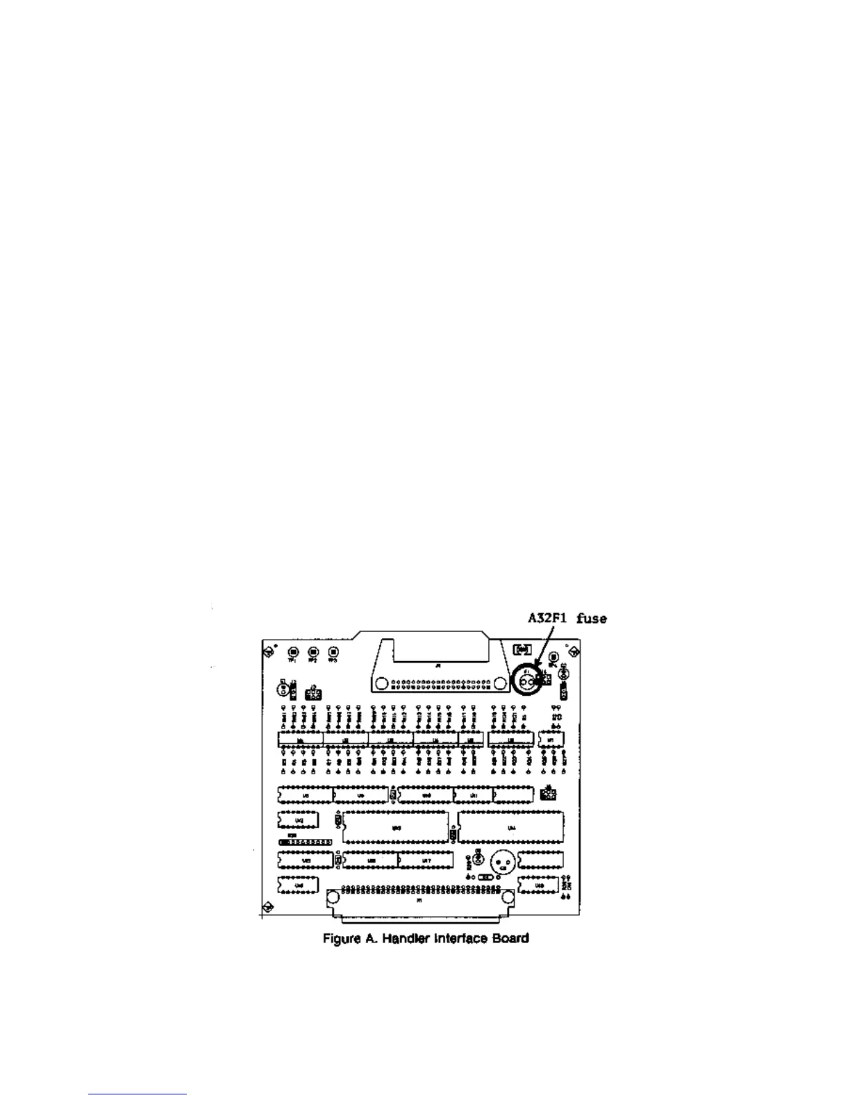
2. Remove A32F1 (indicated in Figure A) from socket and carefully insert the new fuse.
3. Replace the handler interface board, top shield plate, rear feet, and top cover.
If the handler interface continues not to output +5V after A32F1 has been replaced,
contact the nearest Agilent Technologies office.