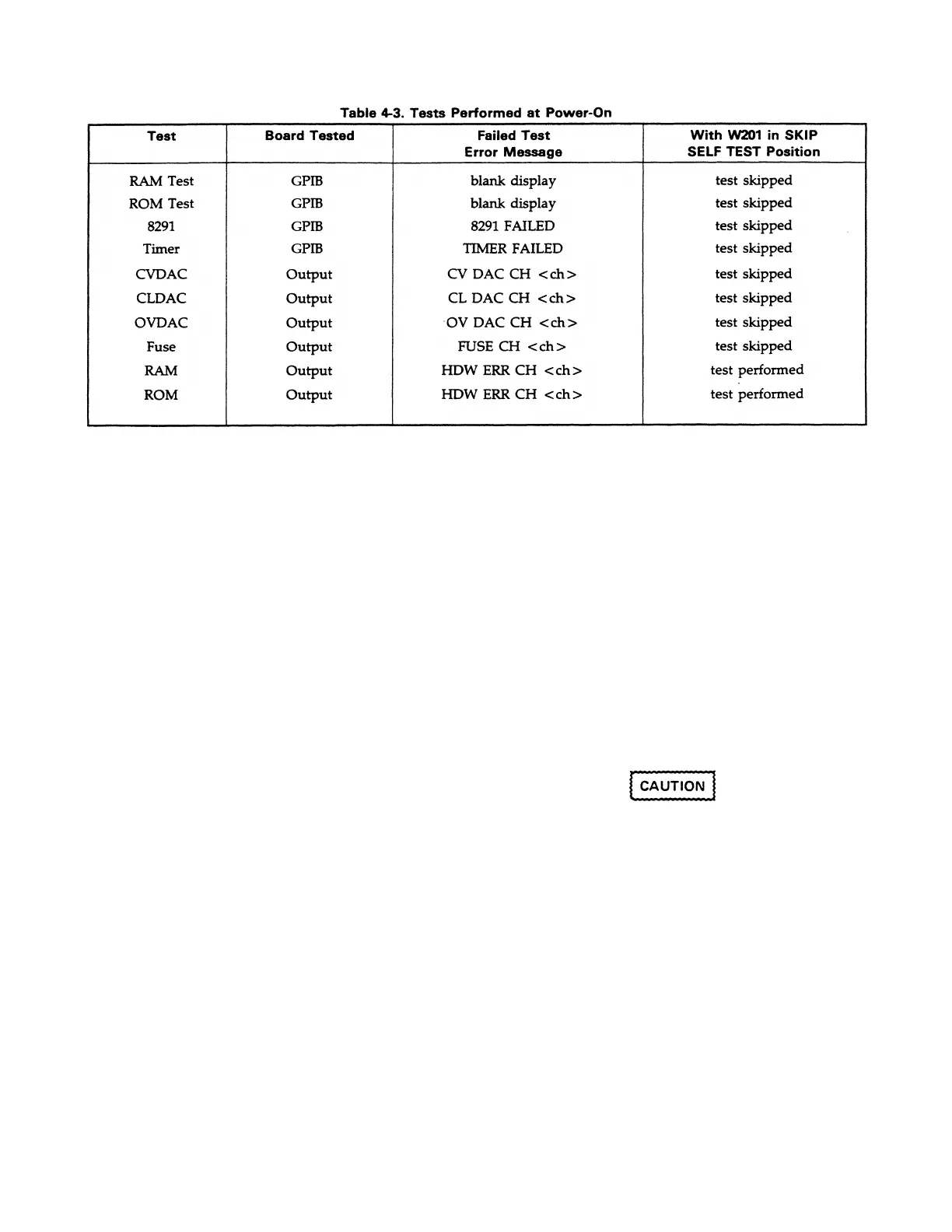
Table 4-4 lists all of the self-test error messages that can
appear on the front panel display when power is first turned
on. Each message is explained and a troubleshooting
procedure is recommended. This table is to be used in
conjunction with Figure 4-5 and other troubleshooting flow
charts provided in this section.
4-16 Connector P201 Jumper Positions
with jumper position that are used for normal operation of
the power supply or troubleshooting. The following
discussion describes the function of each of four jumper
positions.
+ 5 V NORM RUN: This jumper position is used as the
normal running position. The two
pins on P201 that W201 connects in
this position are both tied to the GP
IB board + 5 V bias supply. The
jumper is simply stored in this
position when not used in one of the
other positions.
CAL. LOCKOUT: This position is an alternate to the
NORM RUN position and is used to
ensure against accidental calibration
of the power supply. With W201 in
this position, error number 18 (CAL
LOCKED) is generated if an attempt
is made to turn on the mode (see
Appendix A, calibration in the
Operating Manual).
SIG. ANALYSIS: This position is used to perform
signature analysis on the GPIB board
for troubleshooting the GPIB board
(see para. 4-23).
SKIP SELF TEST: This position causes the power
supply to skip the power-on self tests
described in paragraph 4-15. This
position allows the GPIB board to
attempt to power on all output boards
in the supply even if one or more
output would would not have passed
self test.
Exerci se ca re wh en usi ng SKIP SEL F TEST on a
unit with ou tput bo ards t hat are kno wn to fa il se lf
test si nce th e outp ut may op er ate bey o nd its rated
parameters. The outp ut vo ltage m ay e ven reac h
full sc ale volt age withou t be ing progr amme d.
The GPIB board contains a connector (P201), see Figure 4-2,
4-17 ERROR Codes and Messages
Table 4-5 lists all of the error codes and messages that can
occur when operating the supply. Each code and the
corresponding message (if applicable) are explained and a
remedy or troubleshooting procedure is recommended. This
table is used in conjunction with Figure 4-5 and other
troubleshooting
flow charts provided in this section.
4-8
N
ote that error number 22, SKIP SELF TEST, is initially
generated when W201 is in the SKIP SELF TEST position.
This error is cleared when read. However, if an output
board fails the output board RAM or ROM tests which are
performed regardless of the W201 position, error number 11,
12, 13, or 14 (HDW ERR CH <ch>) is generated and will be
regenerated after the error is read since the problem still
exists.
Artisan Scientific - Quality Instrumentation ... Guaranteed | (888) 88-SOURCE | www.artisan-scientific.com

 Loading...


