EPM Series Power Meter (E4418B) Modification
Appendix A60
Step 10. Figure A-10 shows a different view of the modified Measurement PCB.
Figure A-10
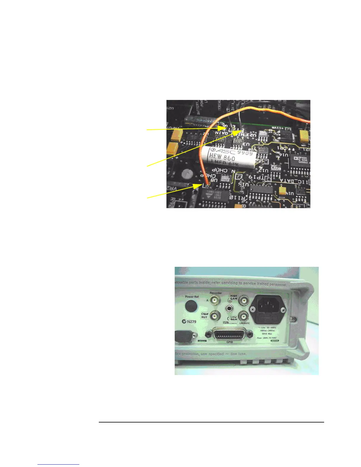
Step 11. Label each of the BNC connectors using the permanent marker and adhesive labels,
as shown in Figure A-11. Refit the cover, handle, and the rear bumper to the power
meter. Tighten both screws with the T-15 torque screwdriver.
Figure A-11
Chop Output
High Gain Output
Low Gain Output