112 Chapter3
Manual Adjustment Procedures
1. IF Bandpass Adjustment
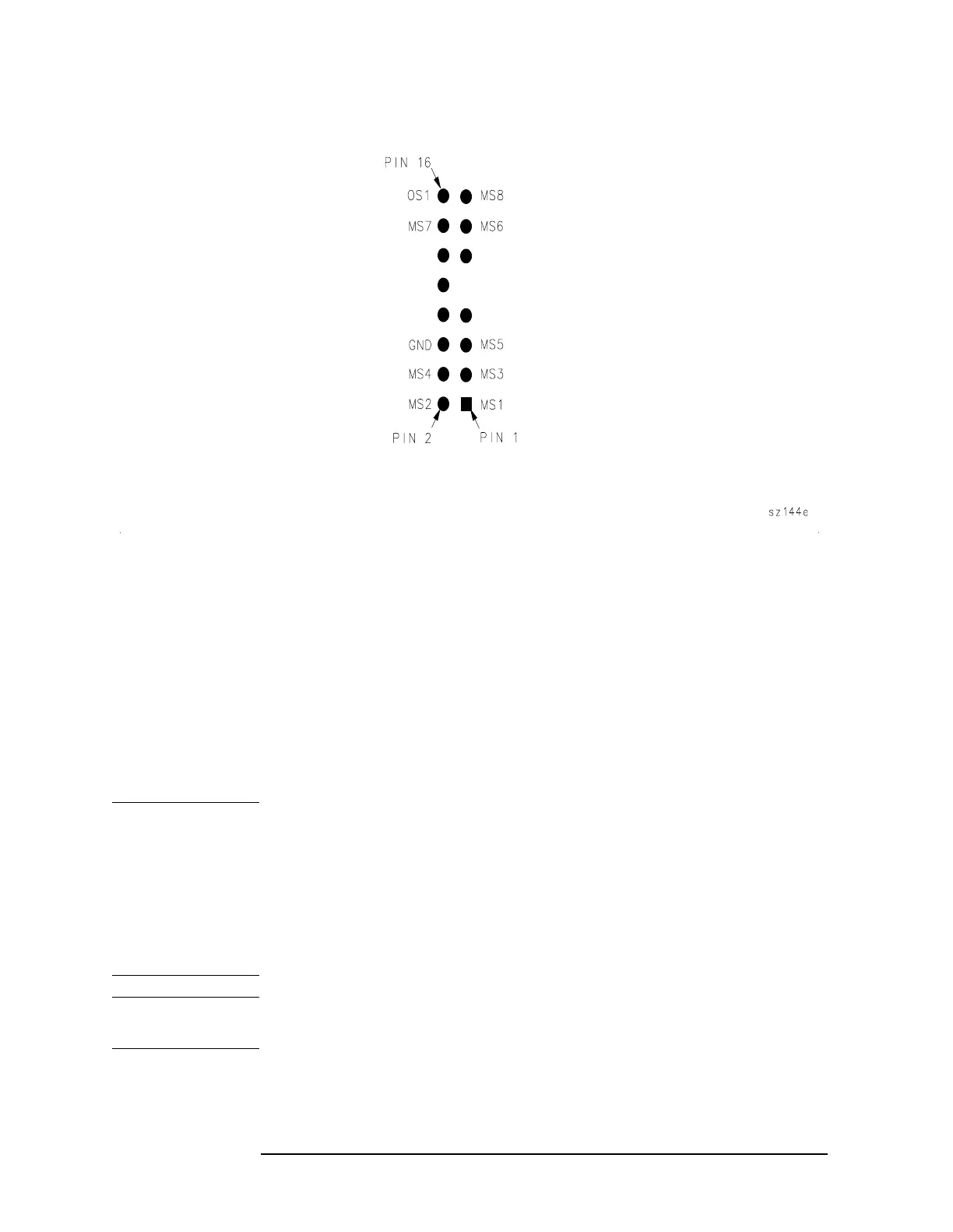
Figure 3-6 A5J6 Pin Locations
LC Bandpass Adjustments
4. On the spectrum analyzer, press ADJ CURR IF STATE. Wait for the
IF ADJUST STATUS message to disappear before continuing with the
next step.
5. Read the voltage on A5TP5 (this is an empty-hole type of test point).
If the voltage is less than +6.06 Vdc, turn A5L300 LC CTR 1
clockwise. If the voltage is greater than +6.26 Vdc, turn LC CTR 1
counterclockwise.
6. Repeat steps 1and 2until the voltage reads +6.16 Vdc ±100 mV.
NOTE If the range for the LC CTR adjustment is insufficient, replace the
appropriate factory-selected capacitor as listed in Table 3-4 on
page 113. To determine the correct replacement value, center the
LC CTR adjustment and press
ADJ CURR IF STATE. After the
IF ADJUST STATUS message disappears, read the DVM display. Choose
a capacitor value from Table 3-5 on page 113, based on the DVM
reading and the presently loaded capacitor value. Table 3-8 on page 115
lists a few capacitor part numbers.
CAUTION Turn the spectrum analyzer off by pressing LINE to the off position
before removing or replacing any shield.
7. Move the positive DVM lead to A5TP6.
8. Adjust A5L301 LC CTR 2 by repeating steps 4 through 6.
 Loading...


