144 Chapter2
Making Adjustments
23. BITG Power Level for Option 010
9. On the analyzer, press SRC PWR ON OFF (ON), 0, dBm, SGL SWP.
Note that some analyzers may have sealing compound over
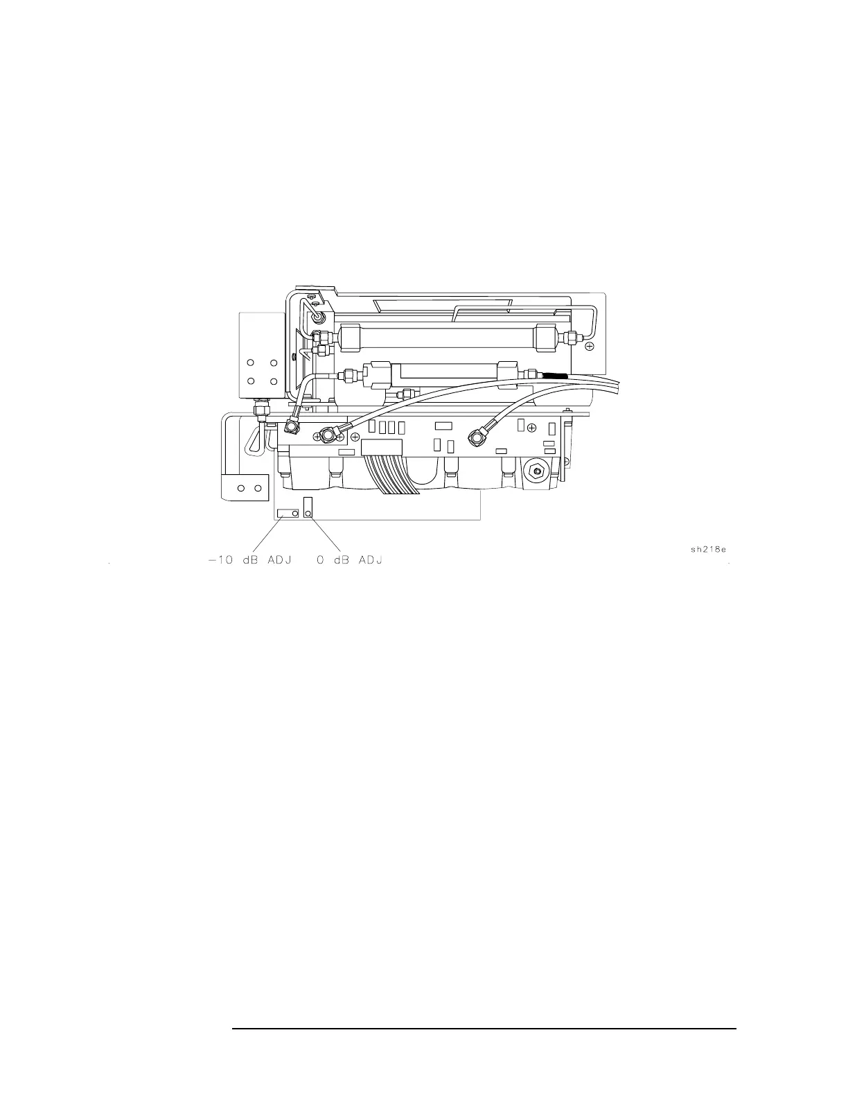
A3A15R13 (−10 dB ADJ) and A3A15R18 (0 dB ADJ) adjustments.
Remove this compound before making these adjustments.
10.Adjust −10 dB ADJ (A3A15R13) for a 0 dBm ±0.05 dB reading on the
measuring receiver. Refer to Figure 2-35 for adjustment location.
Figure 2-35 BITG Power Level Adjustment Locations
11.Set the SRC PWR level to −10 dBm. Note the power displayed on the
measuring receiver.
If the power level is -9.77 dBm to -10.23 dBm, then the adjustment is
complete. If the power level is not within the range, then continue
with step 11.
Power at −10 dBm Setting ______________dBm
If the power level noted in step 10 was outside the range of −10 dBm
±0.23 dB, perform the following:
a. With the SRC PWR level set to −10 dBm, adjust −10 dB ADJ
(A3A15R13) for a −10 dBm ±0.1 dB reading on the measuring
receiver. Refer to Figure 2-35 for adjustment location.
b. Set the SRC PWR level to 0 dBm. Adjust 0 dB ADJ (A3A15R18) for
a 0 dBm ±0.2 dB reading on the measuring receiver. Refer to
Figure 2-35 for adjustment location.
c. Repeat this step until the output power level is within the
tolerances indicated at both the −10 dBm and 0 dBm SRC PWR
level settings. Adjust −10 dB ADJ only with the SRC POWER level
set to −10 dBm, and adjust 0 dB ADJ only with the SRC PWR level
set to 0 dBm.
 Loading...

