Chapter 2 93
Making Adjustments
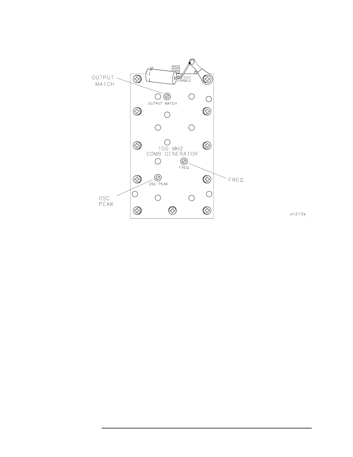
14. Comb Generator
Figure 2-25 Comb Generator Adjustment Location
Procedure
1. Turn the analyzer LINE switch to OFF. Remove the instrument cover
assembly.
2. Remove the front-end assembly. Refer to the “Front-End Assembly”
removal procedure.
3. Remove the A3A1 comb generator assembly from the front-end
assembly and place in a service position, leaving W13 connected to
the A7 Analog Interface.
4. Remove W24 from the A3A1J1 comb generator output connector.
Connect the SMA cable to A3A1J1. Refer to Figure 2-25.
5. Turn the analyzer
LINE switch to ON.
6. Press the following analyzer keys.
AUX CTRL, COMB GEN ON OFF (ON)
 Loading...

